
Professional PCB manufacturing and assembly
Building 6, Zone 3, Yuekang Road,Bao'an District, Shenzhen, China
+86-13410863085Mon.-Sat.08:00-20:00

PCB board device package design specification
First, the purpose:
This specification stipulates the requirements and precautions in the packaging design of the company's product PCB board components, ensuring that the company
The uniformity of all PCB board design and device use of the product facilitates the company's product PCB design requirements and availability
Reliability monitoring, and easy review and filing of product PCBs. This document specifies the components package library design
Some things to note, the purpose is to normalize design, and by solidifying experience into norms,
Avoid mistakes in the design process, and ultimately improve product quality. The point is to train hardware developers
The rigorous and pragmatic work style and serious and serious work attitude of the staff, and enhance their sense of responsibility and mission
sense, improve work efficiency and development success rate, and ensure the reliability of circuit design.
2. Scope:
This specification applies to all PCB board device packaging design specifications in the company's products.
3. Design software requirements:
The PCB electronic circuit design software of Altium Company is uniformly adopted, and the version is Altium 20 software.
4. Overview:
1. When technology developers involve devices that are not in the company’s standardized PCB package library, they shall
The design of the PCB board device package must follow this design specification;
2. When designing the PCB board of the company's products, the device selection should try to use the company's PCB board device package library
The device shall not be designed by itself. If you have any objection to the company's component packaging or have better suggestions,
Please inform the project administrator or superior leader;
3. The company's PCB board device packaging library:
① The company designs and builds the company's general device package library according to the PCB device package design specification.
Resistors, inductors, transformers, integrated circuits, terminals, external processing devices,
Packaging of wire pads, MARK points, mounting holes and other devices;
② There should be non-polar capacitors, electrolytic capacitors, surface mount electrolytic capacitors and other capacitors in the capacitor package.
Device packaging;
PCB Package Design Specifications
③ The daily supplement and improvement of the packaging library is managed by the project administrator.
Five, device packaging design principles:
1. For devices that are not in the company's packaging library, designers can design them by themselves in accordance with this design principle, or submit them to
The R&D director puts forward the design requirements, and the component packaging that can be expected to be used for a long time in the future shall be handled by the R&D
The director arranges personnel to supplement the packaging library;
2. Comply with the device model naming principle, the series of devices with standard packages are named in package form,
Such as surface mount capacitors or surface mount resistors 0805 or 1206;
3. The same size package can have different device models, such as electrolytic capacitors, to avoid borrowing packages;
4. The main factors to be considered in the design of device packaging:
① The ratio of device area to package area should be as close to 1:1 as possible to improve packaging efficiency;
② The pins should be as short as possible to reduce the delay, and the distance between the pins should be as far as possible to ensure that they do not interfere with each other.
improve energy;
③ Based on heat dissipation requirements, the thinner the package, the better.
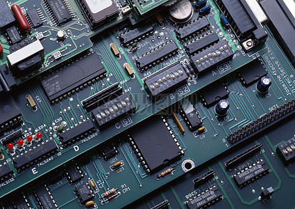
5. Device packaging is mainly divided into:
④ DIP dual in-line;
⑤ SMD patch;
6. Development of device packaging:
① In terms of structure: the earliest transistor TO (such as TO-89, TO92) package has developed to double
In-line package, then the SOP small outline package was developed by PHILIP company, later
Gradually derived SOJ (J-pin small outline package), TSOP (thin small outline package),
VSOP (Very Small Outline Package), SSOP (Shrink SOP), TSSOP (Thin Shrink
SOP) and SOT (Small Outline Transistor), SOIC (Small Outline Integrated Circuit), etc.;
② In terms of material medium, including metal, ceramics, plastics, and plastics, many high-strength
There are still a large number of metal packages for circuits that require working conditions, such as military and aerospace grades;
③ Structure: TO->DIP->PLCC->QFP->BGA->CSP;
④ Material: metal, ceramics -> ceramics, plastics -> plastics;
⑤ Pin shape: long lead in-line -> short lead or leadless mount -> ball bump;
⑥ Assembly method: through-hole insertion -> surface assembly -> direct installation.
Package form of device package:
① SOP/SOIC package: SOP is the abbreviation of English Small Outline Package, namely
small outline package. SOP packaging technology was successfully developed by Philips from 1968 to 1969.
Later, SOJ (J-pin Small Outline Package), TSOP (Thin Small Outline Package),
VSOP (Very Small Outline Package), SSOP (Shrink SOP), TSSOP (Thin Shrink SOP)
And SOT (Small Outline Transistor), SOIC (Small Outline Integrated Circuit), etc.;
② DIP package: DIP is the abbreviation of Double In-line Package in English, that is, double row
In-line package. One of the plug-in packages, the pins are drawn from both sides of the package, and the packaging materials are
Both plastic and ceramic. DIP is the most popular plug-in package, and its applications include standard logic
Logic IC, memory LSI, microcomputer circuit, etc.;
③ PLCC package: PLCC is the abbreviation of Plastic Leaded Chip Carrier in English,
That is, plastic J-lead chip package. PLCC package, square shape, 32-pin package,
There are pins all around and the form factor is much smaller than a DIP package. PLCC package suitable for SMT
Surface mount technology installs wiring on a PCB and has the advantages of small form factor and high reliability
point;
④ TQFP package: TQFP is the abbreviation of English thin quad flat package, that is, thin
Plastic quad flat pack. The quad flat package (TQFP) process can effectively use the space,
Thereby reducing the requirement on the space size of the printed circuit board. Due to reduced height and volume,
This packaging process is ideal for space-critical applications such as PCMCIA cards and
network device. Almost all ALTERA's CPLD/FPGA have TQFP packages;
⑤ PQFP package: PQFP is the abbreviation of Plastic Quad Flat Package in English,
That is, the plastic four-corner flat package. The distance between the chip pins of the PQFP package is very small, and the pins are very
Thin, generally large-scale or very large-scale integrated circuits use this package, the number of pins
Generally above 100;
⑥ TSOP package: TSOP is the abbreviation of English Thin Small Outline Package,
That is, thin small size package. A typical feature of TSOP memory packaging technology is
The pins are made around the chip, TSOP is suitable for SMT technology (Surface Mount Technology) in
Wiring is mounted on a PCB (Printed Circuit Board). TSOP package dimensions, parasitic parameters (electrical
PCB Package Design Specifications
When the current changes greatly, the output voltage disturbance) is reduced, suitable for high-frequency applications, operating
More convenient and more reliable;
⑦ BGA package: BGA is the abbreviation of English Ball Grid Array Package, that is, the ball
grid array package. In the 1990s, with the advancement of technology, the integration of chips continued to increase.
The number of I/O pins has increased dramatically, power consumption has also increased, and the requirements for integrated circuit packaging have become more demanding.
Be stricter. In order to meet the needs of development, BGA packaging began to be used in production. use
The memory packaged with BGA technology can increase the memory capacity while maintaining the same volume
Two to three times, compared with TSOP, BGA has smaller volume, better heat dissipation and
electrical properties. BGA packaging technology has greatly improved the storage capacity per square inch, using
Under the same capacity, memory products with BGA packaging technology are only one-third of the volume of TSOP packaging
One; in addition, compared with the traditional TSOP package, the BGA package has a faster
and an effective way to dissipate heat. The I/O terminals of the BGA package are in the form of an array of circular or columnar solder joints.
distributed under the package, the advantage of BGA technology is that although the number of I/O pins increases, the leads
The pin spacing has not decreased but increased, thus improving the assembly yield; although its
Power consumption increases, but BGA can be soldered with controlled collapse chip method, which can improve its electrical
thermal performance; reduced thickness and weight compared to previous packaging technologies; reduced parasitics,
The signal transmission delay is small, and the frequency of use is greatly increased; the assembly can be coplanar welding, and the reliability is high
RF circuit PCB design processing skills
May 31,2023


Just upload Gerber files, BOM files and design files, and the KINGFORD team will provide a complete quotation within 24h.