
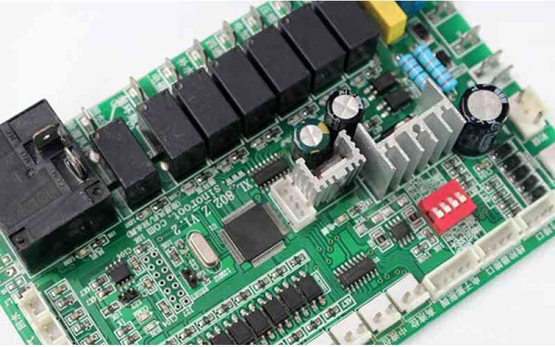
Professional PCB manufacturing and assembly
Building 6, Zone 3, Yuekang Road,Bao'an District, Shenzhen, China
+86-13410863085Mon.-Sat.08:00-20:00

In particular, the design rules related to PCB manufacturing are of practical significance. If the design rules do not meet the requirements of PCB manufacturing process, it will not only affect the function of the product so simple, even can not process can not realize the design intention of the engineer. Therefore, in defining the design rules, it is important to understand the process requirements of the downstream manufacturer for the design.
What are the precision requirements of PCB manufacturing process?
Process requirements of PCB platemaking manufacturers. Including circuit board layer number, thickness, aperture, minimum line width line distance, copper thickness and other basic parameter requirements; Also include plate type, surface treatment, special processing and other special requirements. Generally, when PCB board is processed, it is divided into the proofing processing for testing and the batch product processing for final molding.
For manufacturing precision related process requirements, the most basic and most important are line width and line spacing and minimum aperture. That is, the smallest line width and the smallest hole that the processing plant can handle. If the line width does not meet the requirements in the design, it can not be accurately processed if it is too thin. Line width and line distance accuracy also affect the screen printing layer on the text pattern is clear. If the aperture is too small, there is no bit to support it. The bit size corresponding to the minimum aperture also affects the tolerance accuracy of mechanical holes, mounting holes and other types of plate shear.
Line width, line distance and aperture rule setting precautions
PCB manufacturing process requirements. In terms of PCB manufacturing accuracy, line width, line spacing and aperture rules that meet the requirements and meet the design intention are set. In printed circuit board design, the highest precision supported by batch processing is 3mil line width and line distance. That is, the wiring width must be greater than 3mil and the spacing between two lines must be greater than 3mil. Of course, this is just the minimum line width and line distance. In actual work, the line width needs to be defined as different values according to the design needs. For example, the power network definition is wider, and the signal line definition is thinner. These different requirements can be defined in different network line width values, and then set the priority of rule application according to the importance. Also, for line spacing, define the electrical safety spacing between different networks on the rules page, including line spacing.
There is another special case. For components with high density pins, the spacing between pads within the device is generally very small, such as 6mil. Although it meets the manufacturing requirements of minimum linewidth or spacing greater than 3mil, it may not meet the design requirements as a PCB. If the minimum safe spacing for the entire PCB is set at 8mil, then the spacing of the component pads clearly violates the rule setting. Violations are always highlighted in green during rule checking or online editing. This violation clearly does not need to be addressed, and we should fix the rule setting to eliminate the green highlighting.
Minimum mechanical aperture 0.15mm, small laser aperture 0.1mm
Drilling is unavoidable in PCB design. In terms of design rules and even specific drilling operations, what kind of holes are to be drilled (through hole, blind hole, buried hole, back hole?) And what size hole to drill, do you know? Generally not too complex design, the design of the plate layer is not often used in the through hole. In complex design, especially multi-layer board, high-speed high-density design, PCB wiring space requirements are high, blind holes or buried holes can be set according to the actual needs. Of course, because the manufacturing process of the blind hole is more complex than that of the through hole, the manufacturing cost will increase accordingly.
Difference between mechanical drilling and laser drilling
Drilling is done with different specifications of bit size. If the size of the through-hole aperture in your design is different from the size of the bit available in the processing plant, the bit size closest to your design value will be selected for drilling. The Entry panel is designed to protect the bit and table surface, reduce burrs, and reduce bit temperature. Backup backplate is used to protect the surface of the board against indentation, prevent skid steering and reduce the effect of burr. Drill bits for mechanical drilling are usually ST and UC. In general, UC drilling is more accurate than ST drilling.
Laser drilling is generally used for microholes. With the development of PCB circuit board to micro and high density interconnection, more and more board processing adopts pilot hole connection to achieve high density interconnection. And the ability of traditional mechanical drilling holes, almost to the limit. With the development of blind hole design, the reliability of high density needs to be improved by new technology. Laser drilling comes into being. Laser drilling is much more accurate than mechanical drilling. Therefore, the minimum mechanical hole diameter shall not be less than 0.15mm in the regular setting. The minimum laser aperture should not be less than 0.1mm in the rule. When setting the aperture size, you can refer to the above table to set the appropriate size according to the plate thickness, the number of layers, etc.


Just upload Gerber files, BOM files and design files, and the KINGFORD team will provide a complete quotation within 24h.