
Professional PCB manufacturing and assembly
Building 6, Zone 3, Yuekang Road,Bao'an District, Shenzhen, China
+86-13410863085Mon.-Sat.08:00-20:00

1, the size of 40*30*4mm
2, the endurance of 24 hours
3, USB Type-C charging
4. Charging indicator light
5. Power remaining indicator light
6. You can still work after 1 year of dormancy
7, long press the switch, short press to check the electricity
8. Buzzer alarm device
Product overview specifications
This product is built into the clothing jacket, can measure the temperature and humidity of the human body in real time.
The functions are as follows:
1. The temperature alarm threshold is set to 33 ° C, the absolute humidity alarm threshold is set to 70%RH, the temperature is set to 25 ° C, the temperature offset is set to 0 ° C, and the humidity offset is set to 0%RH
2. After the device is turned on, check the room temperature. If the temperature is higher than the preset room temperature, only the absolute humidity of the sensor is collected.
3. Sensor sampling + offset value > = Threshold, triggering the buzzer
4. After the monitor is turned on, it detects the battery voltage and if it is lower than the 3V threshold, the stroboscopic red LED light (1s once) will automatically shut down after 10 seconds.
5. If the battery voltage is higher than the threshold, the detector flashes a blue LED at an interval of five seconds
6. After sampling and monitoring, the sensor goes into hibernation for 30 seconds. After the hibernation is complete, check the battery power and sample the sensor again
7. Low voltage of lithium battery, stroboscope red LED light during cyclic sampling, automatic shutdown after 15 seconds
Temperature and pressure monitoring box: It is dedicated to monitoring the temperature and pressure of the target environment. When the temperature or pressure of the target environment is higher than the warning value, it will notify the user through the cloud, so that the user can know the situation of the target environment in the first time.
Hardware: 2G communication module, temperature sensor, pressure sensor, processor MCU, battery, battery management IC, display screen, etc
1. This system is composed of two parts: client and upper computer system
2. The client is responsible for monitoring the temperature, pressure (relative to atmospheric pressure) and position of the target environment, and sending the above data to the upper computer through the public data network (4G, or GPRS, etc.)
3. Through the public data network (4G, or GPRS, etc.), the upper computer system will display real-time data received from each client
4. Client system includes: main controller, temperature sensor, pressure sensor, GPS/ Beidou positioning system, data transmission system (4G or GPRS, etc.)
5. The client is powered by a battery (battery model 18650 Lithium battery).
6. The operating temperature range of the client is tentative (-20 ° C to 85 ° C).
7. The temperature detection range of the temperature sensor is tentative (-40 ° C to 125 ° C).
8. The pressure sensor is tentatively differential pressure sensor, and the detection range is tentatively (-0.2bar-5bar).

Intelligent LED light is through the integration of LED and sensing technology, control technology, so that the energy can reach a new height.
Basic functions of intelligent LED, etc. :
1. In the residential corridor scene, when someone enters the sensor detection range, the intelligent channel light will be automatically lit. When the person leaves, the light will be turned OFF after the delay of OFF time.
2, home or shopping mall scene, through the mobile APP control LED light brightness, switch, color and linear change
3, restaurants and other public scenes, through the two-dimensional code on the lamp body, can be used as the entrance for guests to order food
4. In the bar scene, users can deposit the core components of smart LED lights by scanning the two-dimensional code on the lamp body as the entrance of social interaction:
The main components include LED lamp control circuit board, power supply, lampshade, etc
Through the third line on the rail as a signal line (485 signal), control the operation of each car, all cars through the serial bus communication to form the whole logistics network, car has automatic lock protection, fault indication, UV timing disinfection, card management, infrared + physical collision prevention and other functions, can butt HIS;
Details of this PCB design are as follows:
1, support AC24~32V AC input
2. Control three relays, two of which are high-power electronic locks
3. Buzzer warning and alarm
4. wifi networking and server information interaction
5, support serial screen, and communicate with the serial screen
6. The external interfaces are treated with anti-static electricity
7, support NFC serial port card swiping and NFC card key input
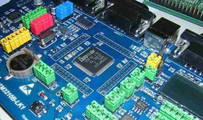
Boards often have to be manually tested and reworked, which requires access to the parts that need to be handled. If these parts are obscured by other larger components, it can make their work more time-consuming or cause collateral damage to adjacent parts. Likewise, connectors, switches, and other inaccessible human interfaces can slow down the manufacturing of boards.
An extremely important guideline is that the layout should start with a basic floor plan of the components on the development board. This will allow you to stratetize how to divide the different circuit areas on the board to avoid overlapping analog and digital signals.

High quality PCB design
Feb 07,2023


Just upload Gerber files, BOM files and design files, and the KINGFORD team will provide a complete quotation within 24h.