
Professional PCB manufacturing and assembly
Building 6, Zone 3, Yuekang Road,Bao'an District, Shenzhen, China
+86-13410863085Mon.-Sat.08:00-20:00

High frequency circuit board material selection and passive intermodulation
PCB manufacturers, PCB designers and PCBA processors will explain the selection of high-frequency PCB materials and passive intermodulation
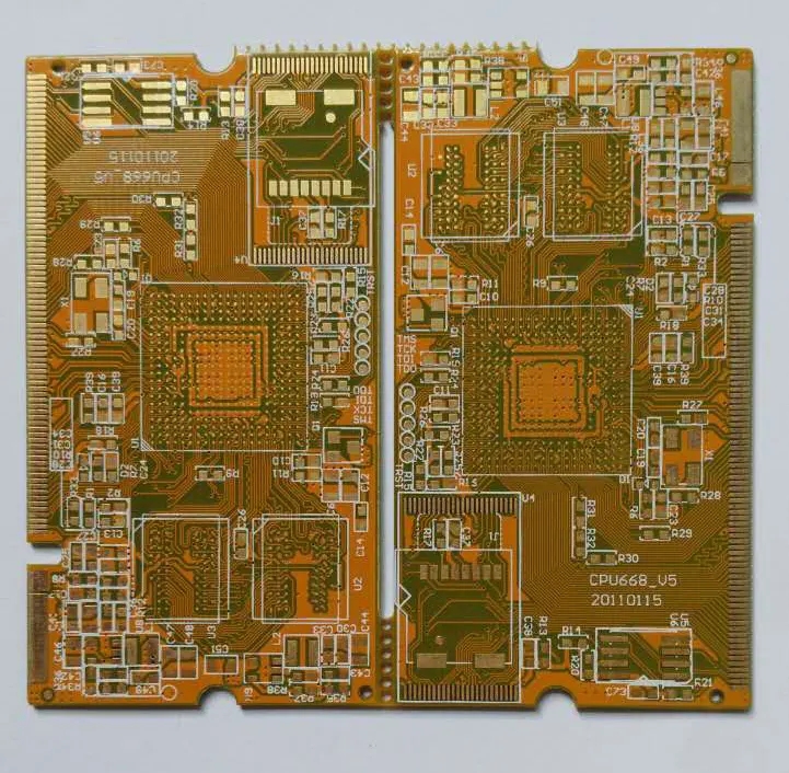
With the development of wireless communications and broadband networks, high-frequency circuit boards are no longer simply laying metal wires on some insulating substrates to achieve interconnection. In many cases, substrates and metal conductors have become part of functional components. Especially in RF applications, components and substrates interact, so the design and manufacture of high-frequency circuit boards have a more and more important impact on the function of products. As shown in Figure 1, a typical part of the high frequency circuit board/microwave board, on which the conductors are all components.
High frequency circuit board
Our high-frequency circuit board manufacturers are also more involved in things related to design, especially in high-frequency and high-speed signal transmission. Similarly, designers must have a deep understanding of the manufacturing process of high-frequency circuit boards to comprehensively produce qualified and high-performance high-frequency circuit boards.
From this issue, we will introduce some parameters that people often contact, and do some technical discussions from the simple to the deep, hoping to deepen the communication and exchange between design and manufacturing.
1. Dielectric constant
Dielectric constant (Dk, ε, Er) determines the speed of electrical signal propagation in the medium. The speed of electrical signal propagation is inversely proportional to the square root of the dielectric constant. The lower the dielectric constant, the faster the signal transmission. Let's make a visual analogy, just like when you run on the beach, the water depth submerges your ankles. The viscosity of water is the dielectric constant. The more viscous the water is, the higher the dielectric constant is, and the slower you run.
The dielectric constant of high-frequency RF circuit board is not easy to measure or define. It is not only related to the characteristics of the medium itself, but also related to the test method, test frequency, and the material state before and during the test. The dielectric constant will also change with the change of temperature, and some special materials will take temperature into account in the development. Humidity is also an important factor affecting the dielectric constant, because the dielectric constant of water is 70, and very little water will cause significant changes.
The following are the dielectric constants of some typical materials (at 1Mhz):
It can be seen that for high-speed and high-frequency applications, the most ideal material is the air medium wrapped with copper foil, Thickness tolerance is+/- 0.00001 ". As a material development, everyone is making efforts in this direction. For example, the Foamclad patented by Arlon is very suitable for the application of base station antennas. However, not all high-frequency RF lines are designed with the smaller dielectric constant, which is often based on some actual designs. Some lines that require very small volumes often need materials with high dielectric constant. For example, Arlon AR1000 is used in miniaturized line design. Some designs are as follows: Power amplifier, commonly used dielectric constant 2.55 (such as Arlon Diclad 527, AD255, etc.), or dielectric constant 3.5 (such as AD350, 25N/FR, etc.). There are also those that adopt 4.5 dielectric constant (such as AD450), which are mainly changed from FR-4 design to high-frequency application, and they hope to continue the previous design.
In addition to directly affecting the transmission speed of the signal, the dielectric constant also determines the characteristic impedance to a large extent. In different parts, the characteristic impedance matching is particularly important in microwave communication. If the impedance mismatch occurs, the impedance mismatch is also called VSWR (standing wave ratio).
CTEr: Since the dielectric constant changes with temperature, and the materials used for microwave applications of high-frequency circuit boards are often outdoors, even in space environments, CTEr (Coefficient of Thermal of Er) is also a key parameter. Some ceramic powder filled PTFE PTFE can have very good characteristics, such as CLTE.
2. Loss, loss tangent, Df, Dissipation factor
In addition to the dielectric constant, the loss factor is an important parameter affecting the electrical properties of materials. Dielectric loss is also known as loss tangent, loss factor, etc. It refers to the loss of signal in the medium, or energy loss. This is because when high-frequency signals (they are constantly changing between positive and negative phases) pass through the dielectric layer, molecules in the medium try to orient according to these electromagnetic signals, although in fact, because these molecules are cross-linked, they cannot really orient. However, the change of frequency makes the molecules keep moving, generating a lot of heat and causing energy loss. However, some materials, such as PTFE polytetrafluoroethylene, are nonpolar, so they will not be affected by the electromagnetic field, so the loss is small. Similarly, the loss factor is also related to the frequency and test method. The general rule is that the higher the frequency, the greater the loss.
The most intuitive example is the consumption of electrical energy in transmission. If the circuit design loss is small. The battery life can be significantly increased. When receiving the signal, the antenna will be more sensitive to the signal and the signal will be clearer by using the lossy material.
The commonly used FR4 epoxy resin (Dk4.5) has relatively strong polarity. At 1GHz, the loss is about 0.025, while the loss of PTFE PTFE base material (Dk2.17) is 0.0009. Compared with glass filled polyimide, quartz filled polyimide not only has low dielectric constant, but also has low loss, because the silicon content is pure.
The following figure shows the molecular structure of PTFE polytetrafluoroethylene. We can see that its structure is very symmetrical, the C-F bond is tightly bound, and there is no polar group. Therefore, the possibility of swaying with the change of electromagnetic field is very small, which is shown in the electrical characteristics of small loss.
3. Thermal conductivity
In many microwave fields, there are many high-power applications. The heat dissipation characteristics of materials can greatly affect the reliability of the entire system. Therefore, the thermal conductivity should also be considered. For some special high reliability and high power consumption applications, metal lining (aluminum base or copper base) can also be used.
4. Manufacturability
We understand that PTFE polytetrafluoroethylene is difficult to process, especially for hole metallization, which requires plasma or sodium naphthalene treatment to improve its activity. Moreover, PTFE polytetrafluoroethylene is a thermoplastic material, and the processing temperature of multilayer boards is high. Now, new low loss thermosetting resin materials have been developed for high-frequency circuits, which can process multilayer circuit boards without plasma activation, such as Arlon 25N/FR. At present, it is widely used in LNA, PA and antenna design. Moisture absorption is also a consideration. Materials with small moisture absorption should be selected as far as possible, so that the electrical characteristics are more stable.
5. Coefficient of thermal expansion (CTE)
The coefficient of thermal expansion of high-frequency circuit boards is usually abbreviated as CTE (CoefficientThermal Efficient), which is one of the important thermal mechanical properties of materials. It refers to the expansion of materials when heated. The actual material expansion refers to the volume change, but due to the characteristics of the substrate, we often consider the expansion in the plane (X -, Y -) and vertical direction (Z -) respectively.
Planar thermal expansion can often be controlled by reinforcing layer materials (such as glass cloth, quartz, Thermomount), while longitudinal expansion is always difficult to control above the glass transition temperature.
The planar CTE is very important for installing high-density packages. If the chip (usually CTE is 6-10ppm/C) is installed on a conventional PCB high-frequency board (CTE 18ppm/C), after multiple thermal cycles, it may cause excessive aging of solder joints under stress. The CTE of Z axis directly affects the reliability of plated holes, especially for multilayer plates.
Generally, the CTE of PTFE polytetrafluoroethylene is relatively large. It is rare to use pure PTFE polytetrafluoroethylene to make multilayer boards. PTFE polytetrafluoroethylene filled with ceramic powder is often used.
It is used on the global communication satellite.
6. Passive Intermodulation (PIM)
The front-end design of HF circuit board in RF, such as antenna and filter, requires passive intermodulation, which is also related to the base material of HF circuit board. Some companies use specific copper foil to keep passive intermodulation in a certain range. The following table shows the difference between the high-frequency circuit board board without passive intermodulation requirements and the high-frequency circuit board board PIM with specific requirements.
Passive Intermodulation Causes
Passive intermodulation is mainly generated by passive nonlinearity, which usually has two types: one is the nonlinearity caused by metal contact, and the other is the inherent nonlinearity of the material itself. For example, coaxial cables and connectors are generally considered to be linear, but their nonlinear effects are shown in the case of high power. Slight nonlinearity does exist in the contact of cable braids, the threads of connectors and other metal joints. Each surface of these metal contacts has a thin insulating layer formed by metal oxidation. It is this contact nonlinearity that generates low-level passive intermodulation interference, which can seriously degrade the performance of the receiver.
The reason for metal contact nonlinearity is mainly the looseness and corrosion of the joints. Its volt ampere characteristic is a curve. The specific main mechanisms are as follows:
1) Non linearity caused by poor installation technology;
2) Nonlinearity related to large current at metal contact;
3) Nonlinearity related to metal surface fouling, metal particles and carbonization;
4) Second electron multiplication effect through the sand hole and micro slit in the metal structure;
5) Electron tunneling effect and semiconductor behavior through thin oxide layer (thickness less than 50Ao) at metal contact;
6) Thermal cycle of relative motion of metal contact surface caused by strong current.
There is no strict limit between linear and nonlinear. Metal contact is usually considered as linear, but it shows nonlinear effect under high power.
The nonlinear effect can not be completely eliminated and can only be reduced as far as possible. The main reduction measures are:
1) Keep the minimum thermal cycle and reduce the non-linear contact caused by expansion and compression of metal materials.
2) Minimize the number of metal contacts. For example, use choke connections or other dielectric connections to provide sufficient current channels to keep all mechanical connections clean and tight.
3) Try to avoid using tuning screws or metal or metal contact moving parts on the current channel. If necessary, they should be placed in low current density areas.
4) Improve the connection process of materials. Ensure that the connection is reliable and there is no gap, pollution or corrosion as far as possible.
5) The current density on the conductive channel shall be kept low. For example, the contact area should be large, and the conductor block should be large.
Due to the complexity of passive intermodulation problem, it is difficult to establish a high-power circuit model, so some analysis methods of nonlinear circuits cannot be used. However, for metal contact nonlinearity, it can be represented by a simple system as shown in Figure 4, where X and Y represent input and output signals (current or voltage) respectively. The generation process of the entire metal contact nonlinearity is simulated by a single transfer function, and the input output method is used for analysis, The specific solution methods mainly include power series method and Volterra series method. Because the power series method has the advantages of simple use, fast calculation speed and easy implementation, this method is adopted in this paper.
Summary
The selection of microwave materials for high-frequency circuit boards mainly depends on dielectric constant, loss, thermal expansion coefficient and thermal conductivity.
Low cost, low loss, thermosetting, high dielectric constant ceramic filled PTFE polytetrafluoroethylene, low dielectric constant, low loss, PTFE polytetrafluoroethylene, CTEr stabilized ceramic filled PTFE, low cost, commercial PTFE polytetrafluoroethylene. PCB manufacturers, PCB designers and PCBA processors will explain the selection of high-frequency PCB materials and passive intermodulation.


Just upload Gerber files, BOM files and design files, and the KINGFORD team will provide a complete quotation within 24h.