
Professional PCB manufacturing and assembly
Building 6, Zone 3, Yuekang Road,Bao'an District, Shenzhen, China
+86-13410863085Mon.-Sat.08:00-20:00

How to judge the welding quality of BGA slice
Because there are just a few photos of BGA solder after slicing your own products, which can be used as teaching materials. There are also typical photos of HIP, Head In Pillow and solder ball being pulled. Usually, when you get a BGA slice photo, the first thing to judge is which side belongs to the BGA packaging surface and which side belongs to the circuit board assembly surface. For this problem, my method is to judge from the thickness of the copper foil. The thicker side of the copper foil is usually the assembly surface of the circuit board. Because the carrier board of the BGA package is usually thinner than the circuit board of the electronic assembly, the thinner copper foil is chosen.

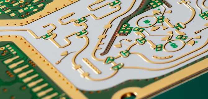
Secondly, if the double ball phenomenon can be clearly seen (as shown in the following figure, it is a typical HIP false cold welding defect), the larger side of the ball is usually the original solder ball on the carrier plate, because the volume of the BGA solder ball has been reflow once, while the volume of the solder paste printed on the PCB after a reflow flux volatilization is only half of the original volume, so the ball on the BGA side is usually large. As for the size of the solder pad (pad), it is not certain. It depends on whether the wiring design of your own PCB is consistent with [Cooper Define Pad Design]. Then judge whether BGA welding is good or bad. The figure below clearly shows the typical [HIP] welding problem. Those who don't know about it can click the [HIP (Head in Pillow Effect)] link for further discussion. 99% of the HIP should occur on the outermost row of solder balls around the BGA. The reason is that almost all BGA carrier plates or PCB are deformed and warped when they are Reflow, and the deformation becomes smaller after the board is warmed up, but the molten tin has cooled, So it forms the appearance of two balls leaning together.
HIP is a serious BGA solder defect. It is easy to flow to the customer through the factory test program, but after a period of use, the product will be sent back for repair because of problems. The second type of BGA solder defect is a solder ball between HIP and normal solder. Do you know how to judge which side is the PCB end? From the figure below, it can be seen that the BGA solder ball and the solder paste on the PCB have been completely melted together, because there is no double ball visible, but the entire solder ball is pulled up and down long and almost broken. By observing the solder on the PCB surface, it can also be found that the contact area between the solder ball and the PCB pad is smaller, and there is also an angle of no length, because the solder ball is pulled up and down.
This kind of solder fracture should only be a matter of time. The vibration when the client should be used or the thermal expansion and cold contraction during the switching process will accelerate the fracture. The BGA solderball welding in the following figure is acceptable. The ball also has solder that is flattened to form a horizontal oval, but it can be seen that the solder ball near the PCB end is still slightly pulled apart. In fact, a better solder ball shape should be like the following picture. The solder ball is similar to a "lantern" and covers the entire PCB pad. However, sometimes the welding pad is designed to be covered with green oil, and its shape will be similar to the above figure.


Just upload Gerber files, BOM files and design files, and the KINGFORD team will provide a complete quotation within 24h.