
Professional PCB manufacturing and assembly
Building 6, Zone 3, Yuekang Road,Bao'an District, Shenzhen, China
+86-13410863085Mon.-Sat.08:00-20:00

PCB manufacturing technology includes computer aided manufacturing processing technology, namely CAD/CAM, and photo drawing technology. The general process of photo drawing technology is: check file to determine process parameters CAD file to Gerber file CAM processing and output. 1、 Computer Aided Manufacturing Division
PCB manufacturing technology includes computer aided manufacturing processing technology, namely CAD/CAM, and photo drawing technology. The general process of photo drawing technology is: check file to determine process parameters CAD file to Gerber file CAM processing and output.
1、 Computer Aided Manufacturing Processing Technology
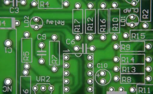
Computer aided manufacturing (CAM) is a process processing based on the PCB process. All the process requirements mentioned above should be prepared before photo painting. For example, mirror image, PCB solder mask expansion, process line, process frame, line width adjustment, center hole, contour line and other issues should be completed in the CAM process. Special attention shall be paid to the places where the middle distance of the user file is too small.
Because the process flow and technical level of each factory are different, to meet the final requirements of users, necessary adjustments must be made in the manufacturing process to meet the user's requirements on accuracy and other aspects. Therefore, CAM processing is an essential process in modern printed circuit manufacturing.
1. Work completed by CAM
① Correction of pad size, combined with D code.
② Correction of line width, combined with D code.
③ Check the minimum spacing between pads, pads and lines, lines and lines.
④ Inspection and splicing of aperture size.
⑤ Check the minimum lineweight.
⑥ Determine the expansion parameters of resistance welding.
⑦ Mirroring
⑧ Add various process lines and process boxes.
⑨ The line width is corrected to correct the side erosion.
⑩ Form a central hole.
2. Organization of CAM operations
As there are dozens of popular CAD software on the market, the management of CAD processes must start from the organization first, and a good organization will achieve twice the result with half the effort. As Gerber data format has become the standard of photo industry, Gerber data should be taken as the processing object in the whole photo process. Taking CAD data as an object can cause the following problems.
(1) There are too many kinds of CAD software. If various process requirements are to be completed in the CAD software, every operator is required to master the operation of each CAD software. This will require a long training period to enable operators to become skilled workers and meet the actual production requirements. This is not cost-effective in terms of time and economy.
(2) Due to various process requirements, some requirements cannot be realized for some CAD software. Because CAD software is used for design, it does not take into account the special requirements in process processing, so it cannot meet all requirements. CAM software is specially used for process processing, and it is the best to do these jobs.
(3) CAM software has powerful functions, but all of them operate on Getber files instead of CAD files.
(4) If CAD is used for process processing, each operator is required to be equipped with all CAD software, and each CAD software has different process requirements. This will cause unnecessary confusion to management.
To sum up, the CAM organization should be the following structure (especially large and medium-sized enterprises).
① All process processing takes Gerber data as the processing object.
② Each operator must master the skills of converting CAD data to Gerber data.
③ Each operator must master the operation methods of one or more CAM software.
④ Develop a unified pcb process specification for Gerber data files.
⑤ CAM operations can be managed by several operators in a relatively centralized manner.
A reasonable organization will greatly improve the management efficiency and production efficiency, and effectively reduce the error rate, so as to achieve the effect of improving product quality.


Just upload Gerber files, BOM files and design files, and the KINGFORD team will provide a complete quotation within 24h.