Rigid-flex PCB design
Rigid-flex PCB design
The rigid-flex PCB design process requires careful consideration of several key factors. These include industry regulations, size and shape constraints, board stacking requirements, and possible design optimization solutions. The purpose of this guide is to clarify these considerations and help you determine the best way to design a rigid-flex PCB.
Rigid-flex PCB design
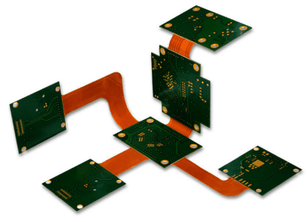
Rigid-flex PCB design is the process of creating printed circuit boards that combine the rigidity of a standard rigid PCB with the flexibility of interconnecting flex circuits. This combination allows for more efficient use of space and easier connection. It also reduces PCB weight compared to traditional rigid designs.
During the design process, engineers use software tools to create a PCB model. This model is used to represent the board stackup, size and shape requirements, and all other details required for a successful rigid-flex PCB design.
Given their unique characteristics, designing rigid-flex PCBs requires compliance with industry regulations and other requirements. Below, we will take you through the main factors of rigid-flex PCB design.
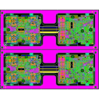
Rigid-Flex PCB Layer Stackup
Rigid-Flex PCB Layer Stackup
Resources: https://www.researchgate.ne
Rigid-Flex PCB Design Guidelines
How do you ensure a successful rigid-flex PCB design? While specific design rules may vary by application, some general guidelines apply and should be followed. These include rules for rigid-flex PCB materials, stackups, bend radii, impedances, and via characteristics.
Rigid Flex PCB Material
Rigid-flex PCB materials include materials for rigid parts and flexible parts. Also, each part has material options. According to IPC standards, materials must meet certain requirements. In general, the considerations for material selection are as follows:
fire performance
Moisture resistance
Glass transition temperature, also abbreviated as Tg
Coefficient of Thermal Expansion or CTE
chemical resistance, and
Dielectric constant or Dk
The choice of rigid-flex PCB material depends on the application, cost and performance requirements. For rigid parts, FR4 and polyimide are commonly used. These materials have excellent insulation, heat resistance and flame retardancy.
For flexible parts, popular choices are polyimide or Kapton films, as these materials have very low Dk and CTE values. In addition, they have good thermal stability and chemical resistance.
Rigid-Flex PCB Stackup
PCB stackup refers to the arrangement of circuit board layers. When designing a rigid-flex PCB stackup, engineers must consider the number of layers, the type of material for each layer, and other design elements needed for a successful board.
One of the rules of rigid-flex PCB layup is to optimize it to the application requirements. This includes ensuring the correct board thickness for different sections, number of layers and material types.
Rigid flexPCB thickness determines its bendability in the flexible part and strength in the rigid part. For successful performance, the thickness must meet specific requirements. Generally, if you want to bend the flexible part repeatedly during use, it is not recommended to exceed 2 layers.
Rigid Flex PCB Bend Radius
Bend radius is a key factor in rigid-flex PCB design. It determines how much space is needed to bend the flex portion of the board. It also determines the suitability of the board for static or dynamic flex applications.
To ensure successful performance, rigid bend radii must be kept within a certain range, typically using a ratio of bend radius to board thickness. The bending rate is obtained by dividing the bending radius by the plate thickness.
Depending on the application, your manufacturer should be able to provide minimum and maximum ratios for the bend radius of the rigid-flex PCB.
For a 1-layer rigid-flex PCB section, a bend ratio of 10:1 for static applications and 100:1 for dynamic applications is recommended.
For 2-layer boards, a ratio of 10:1 is suitable for static board applications and a ratio of 150:1 is suitable for dynamic use cases.
If multiple layers are used in a flexible part, a 20:1 bend ratio is used for static applications. Due to the increased thickness, this type of board should not be used for dynamic application PCBs.
Rigid Flex tor iPCB Impedance
Impedance is an important factor in the rigid-flex PCB design process. It refers to the reaction of a circuit or component to alternating current. High impedance in flex circuits can cause signal reflections, loss of signal integrity, and other problems.
To optimize the performance and reliability of high-frequency circuits, engineers must ensure controlled impedance at the design level. To control rigid-flex PCB impedance, factors that affect it must be considered. These include trace width, dielectric material thickness and copper thickness or weight.
Engineers can use design software to automatically calculate the precise impedance of rigid-flex circuits. This will ensure that impedances are properly matched in the circuit, improving performance and signal integrity.
Rigid Flex PCB Vias
Vias are metalized holes that connect different layers of a circuit board. During rigid-flex PCB design, it is important to follow certain rules when adding vias, as these can affect the performance and durability of the finished product.
Avoid Vias in Flex Areas of Rigid-Flex PCBs—or Use Them Sparingly
Use teardrops to route copper traces to vias. Teardrop shape provides extra strength and reduces stress
In rigid parts, avoid placing vias near edges. Instead, ensure a distance of at least 50 mils
With the right combination of materials, stackup, bend radius, impedance, and vias, when designing PCBs for rigid-flex, engineers can create boards optimized for their application requirements with superior reliability, flexibility, and thermal performance.
Summarize
Given the unique structure and requirements of a product, rigid-flex PCB design must consider several factors to ensure that the board is suitable for its intended application. This includes design rules based on thickness and bend radius, as well as impedance and vias.
- Previous:HDI Rigid-Flex PCB Layout & Design
- Next:No