Central air conditioning temperature controller, also known as fan coil temperature controller, is specially designed for the control of fan coil development. Widely used in heating, cooling, ventilation and other HVAC control. The speed of the fan can be manually controlled or automatically controlled by adjusting the wind speed button to achieve the purpose of maintaining the indoor temperature.
The temperature controller of central air conditioning is divided into two kinds: mechanical temperature controller and electronic temperature controller. According to the different display mode is divided into mechanical regulation thermostat and liquid crystal thermostat two.

Electronic thermostat is also known as liquid crystal thermostat. The liquid crystal temperature controller is compared with the measured temperature and the set temperature by the electronic logic circuit, which controls the fan and water valve at the end of the central air conditioner, etc., widely used in hotels, office buildings, shopping malls, industry, medical treatment, especially villas and other civil buildings, so that the controlled environment temperature is constant within the set temperature range, this electronic temperature controller can be optional remote control, which can achieve remote control.
Advantages of central air conditioning LCD thermostat:
1, the appearance of beautiful, generous;
2, MCU control technology, stable and reliable performance, high control accuracy;
3, transformer power supply, safe and reliable. The disadvantages of the central air conditioner LCD thermostat: compared with the mechanical thermostat, the cost is higher. Usage: Generally used in places with high requirements for air conditioning comfort adjustment. The advantages of central air conditioning mechanical thermostat: simple control, less investment costs.
Disadvantages of central air conditioning mechanical thermostat:
1, the appearance is old and stiff;
2, the control accuracy is poor;
3, easy to ignite (direct switching of strong electricity);
4. It is easy to open and close the water valve (or air valve) frequently within a very small temperature difference range;
5, the function is relatively single.
Usage: Generally used for air conditioning comfort adjustment requirements are not high places.
The above is some of the introduction of the central air conditioning thermostat, after understanding some knowledge of the central air conditioning thermostat, how do we change to buy high-quality central air conditioning thermostat?
Remember the following six core to identify the quality of the central air conditioning thermostat.
1, the main control chip is the key;
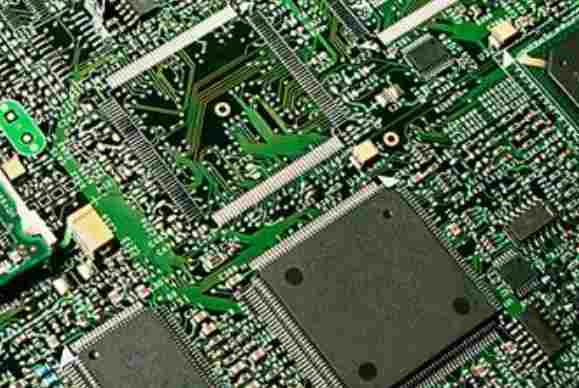
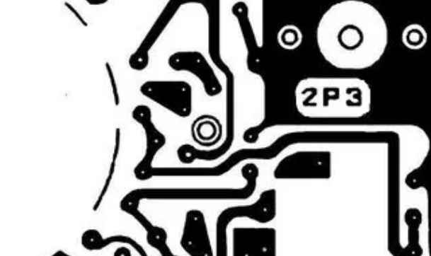
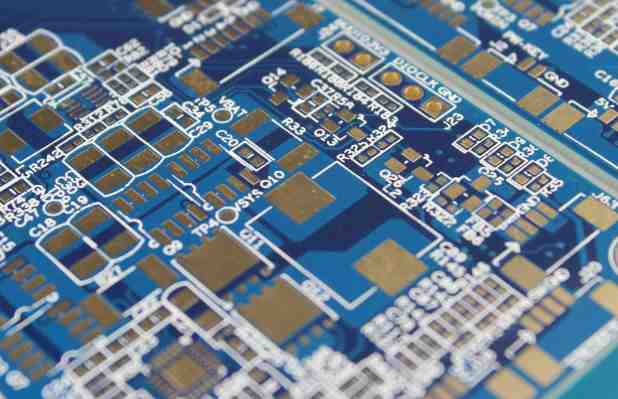
2, PCB integrated circuit protection
3, high-precision sensor NTC is the key
4, the power supply determines the life.
5, the panel selection is exquisite
6, LCM display module is very important.
It is very important to ensure the integrity of the metal shield as much as possible, so the digital signal line into the metal shield should go as far as possible, and it is best to set the next layer of the signal line layer as the ground layer. The RF signal line can go out from the wiring layer of the small gap at the bottom of the metal shield and the grounding gap, but the gap should be surrounded by a large grounding area as far as possible, and the grounding on the different signal layers can be connected by multiple holes. Despite these drawbacks, metal shields are still very effective and often the only solution for isolating critical circuits.
5, power decoupling circuit
A proper and effective chip power decouple circuit is also very important. Many RF chips with integrated linear wiring are very sensitive to power supply noise, and typically require up to four capacitors and an isolated inductor per chip to filter out all power supply noise.
The minimum capacitance value usually depends on the resonant frequency of the capacitor itself and the pin inductance, and the value of C4 is chosen accordingly. The values of C3 and C2 are relatively large due to their own pin inductance, so the RF decoupling effect is poor, but they are more suitable for filtering out lower frequency noise signals. RF decoupling is done by inductance L1, which prevents the RF signal from being coupled from the power cord to the chip. Because all the wiring is a potential antenna that can both receive and transmit RF signals, it is necessary to isolate the RF signal from the critical wiring and components.
The physical location of these decoupled components is also often critical. The layout principle of these important components is: C4 should be as close as possible to the IC pin and grounded, C3 must be closest to C4, C2 must be closest to C3, and the IC pin and C4 connection line should be as short as possible, the ground terminal of these components (especially C4) should usually be connected to the chip's ground foot by the first ground layer on the board. The hole connecting the component to the ground layer should be as close as possible to the component pad on the PCB board. It is best to use a blind hole in the pad to minimize the inductance of the connecting line. The inductance L1 should be close to C1.
An integrated circuit or amplifier often has an open collector, so a pullup inductor is required to provide a high-impedance RF load and a low-impedance DC power supply, and the same principle applies to decoupling the power end of this inductor. Some chips require multiple power supplies to work, so two or three sets of capacitors and inductors may be needed to decouple them separately, and if there is not enough space around the chip, the decoupling may not work well. In particular, it is necessary to pay special attention to the fact that the inductors are rarely parallel to each other, because this will form an air-core transformer and generate interference signals from each other, so the distance between them should be at least equivalent to the height of one of them, or arranged at right angles to minimize mutual inductance.


