
Professional PCB manufacturing and assembly
Building 6, Zone 3, Yuekang Road,Bao'an District, Shenzhen, China
+86-13410863085Mon.-Sat.08:00-20:00

The appearance of PCB board which some forms of disposal: so far the common PCB appearance disposal forms have the following: PCB chemical silver deposition, between OSP and chemical nickel plating/gold leaching, the process is simple and rapid. Exposed to heat, humidity and pollution, it can still provide excellent electrical properties and maintain satisfactory weldability, but it will miss shine. Because there is no nickel under the silver layer, so silver does not have all the good physical strength of electroless nickel plating/gold leaching; Nickel-gold plating, the PCB surface conductor is first electroplated on a layer of nickel and then electroplated on a layer of gold, nickel plating is mainly to avoid the gap between gold and copper. There are two types of nickel gold plating today: soft gold plating (pure gold, which means it does not look bright) and hard gold plating (flat, smooth and hard, wear-resistant, including cobalt and other elements, which looks cleaner). Soft gold is mainly used in chip packaging gold wire; Hard gold is mainly used in electrical interconnections in places that are not burnt (e.g. gold fingers).
Copper coated electronic glass fiber cloth is to thin progress, in order to satisfy the electronic products of short, small, light, thin, high density of the assembly requirements, improve the circuit board to multi-layer, super multi-layer progress. In 2000, the Chinese mainland copper cladding plate industry is 7628 cloth (belonging to thick cloth), accounting for 80 percent of the total dosage, the use of 2116 and 1080 cloth (belonging to thin cloth) accounted for 20 percent of the total dosage has been advanced to the thick cloth accounted for 60 percent, the thin cloth accounted for 40 percent. The proportion of PCB circuit board type
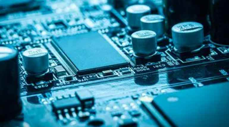
Place the parts with high power consumption and high heat dissipation close to the best heat dissipation position. Do not place high heating parts on the corners and edges of the printed board, and do not place radiators near it. It is possible to select larger components when presetting the power resistance, and to allow sufficient cooling space when debugging the printed board layout. Prevent the concentration of hot spots on the PCB, as far as possible to evenly spread the power on the PCB board, maintain the PCB surface temperature performance average and exactly the same. Often preset process to achieve strict average distribution is more difficult, but must prevent the power density is too high in the area, so as not to reveal the hot spot affect the normal office of the whole circuit. If conditions are available, the implementation of printed circuit thermal performance analysis is very indispensable, such as now a little professional PCB preset software to increase the thermal performance index analysis software plate, you can help preset positions to optimize the circuit preset.
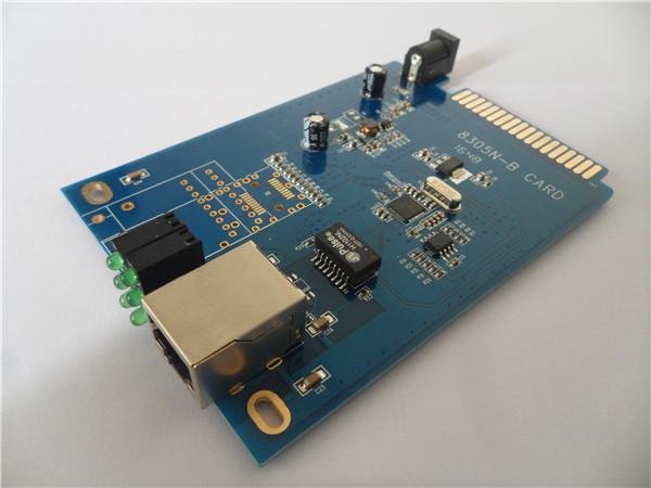
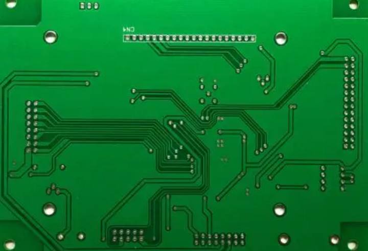
Add: Applied copper for ground wire network, can reduce the impedance of pipe. Electrical boundary: Used to confirm the size of the circuit board. All components on the circuit board cannot exceed this boundary. There are three main categories, circuit boards systems are classified as: boards, boards Single-SidedBoards We just talked about that, so we call this type of PCB Single-sided. Only early circuits used such wrenches because the single panel had a number of strict limits on the preset line (because there was only one side, the wiring could not be crossed and had to be wound in a separate way).
Why is there so much information? You may think of the Internet, which has brought us closer to the world, allowing you to understand different information in a nearly closed background, but have you ever disassembled the main engine of your computer? Or a laptop, will you find it has tens of millions of circuit boards, of course you do not understand many of them, and in your eyes some small, but please do not underestimate it, without them, you want information is impossible to show in front of your eyes. And as the economy has progressed, boards and circuit boards have become much smaller.
Printed circuit presupposition generally through the following steps:
(1) Confirm PCB style, sub-board, number of board layers and co-signing method;
(2) rule the layout of the whole plate;
(3) Wiring Common wiring and layout often need to repeat several times in order to meet the effect. Scientific layout, in the presupposition, layout is a close link. The final result of the layout will directly affect the effect of the layout, because it can be felt that a reasonable layout is the first step of the success of PCB presets. After the mechanical size of PCB is firmly established, confirm the PCB surface size according to the installation form and installation position of the printed circuit board. Then firmly establish the location of the special element. Finally, the layout of other components is implemented according to the function of each unit.
Local material composition of circuit board: circuit board, this knowledge is big, not the same circuit board, the material is not the same, we will enumerate several common copperplate introduction, the main material of printed board is copperplate, and copperplate (copperplate) is composed of substrate, copper foil and adhesive. The substrate is an insulating layer board composed of polymeric resin and reinforced material. The surface of the substrate is covered with a layer of high conductivity, welding performance satisfactory pure copper foil, commonly used thickness of 35 ~ 50 / ma; The copper-covered plate covered by copper foil on one side of the substrate is called single-sided copper-covered plate, and both sides of the substrate are covered by the copper-covered plate of copper foil.
The utility of printed circuit board in electronic machine facilities is: for junction transistor, integrated circuit, resistor, capacitor, inductor and other components to provide fixed and assembled mechanical support; Successfully realized junction transistor, integrated circuit, resistance, capacitance, inductance and other components of wiring and electrical cosignation, electrical insulation to satisfy its special electrical properties; It provides misidentification characters and graphics for the detection and maintenance of components in electronic assembly process, and solder resistance graphics for wave soldering. In the electronic machine facilities because of the appropriate use of printed circuit boards, to prevent the manual wiring error, the successful realization of semi-automatic insertion, welding and testing. Therefore, the quality and reliability of electronic machine products are guaranteed, and the labor production rate is increased, the production capital is reduced, and the maintenance is convenient.
How to prevent high-frequency interference? The basic thinking clue to prevent high-frequency interference is to try to reduce the interference of high-frequency signal electromagnetic field, which is called crosstalk. It can be used to enlarge the distance between the high-speed signal and the analog signal, or to add to the edge of the analog signal. Also pay attention to the digital ground to mimic the noise interference. How to solve the problem of signal integrity in high speed presets? Signal integrity is basically a matter of impedance matching. The factors that affect the impedance matching include the architecture of the signal source and the output impedance, the special property of the wire, the special property of the load side, the topology architecture of the wire, etc. The solution is in the form of end-to-end and debugging wiring topology.


Just upload Gerber files, BOM files and design files, and the KINGFORD team will provide a complete quotation within 24h.