
Professional PCB manufacturing and assembly
Building 6, Zone 3, Yuekang Road,Bao'an District, Shenzhen, China
+86-13410863085Mon.-Sat.08:00-20:00

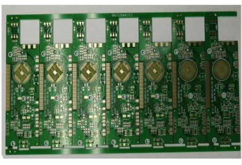
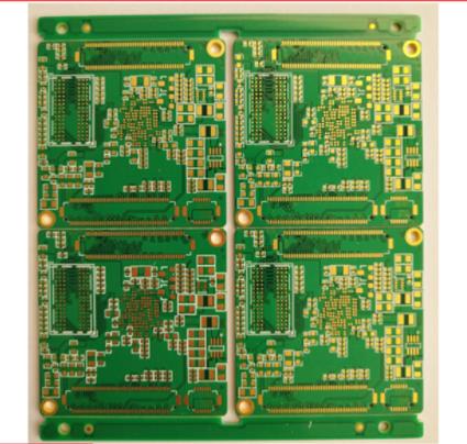
High frequency board/high-speed PCB production and layout skills
Circuit board manufacturing, circuit board design and PCBA processing manufacturers will explain the high frequency board/high-speed PCB manufacturing and layout skills
High frequency boards are used more and more in the high frequency and high-speed field, especially the Rogers series of high frequency boards (microwave RF boards). High frequency boards need a lot of skills in manufacturing, otherwise it will affect the correlation between devices.
1、 The lead between pins of high-speed electronic equipment shall be bent as little as possible
The lead wire of high frequency circuit wiring should preferably be straight line, which needs to be switched. 45 degree broken line or circular arc rotation can be used. This requirement is only used to improve the fixation strength of copper foil in low-frequency circuits, while in high-frequency circuits, satisfying this requirement can reduce the external transmission and mutual coupling of high-frequency signals.
2、 The shorter the lead between pins of high-frequency circuit equipment, the better
The radiation intensity of the signal is in direct proportion to the routing length of the signal line. The longer the signal lead of the high-frequency board (microwave RF board) is, the easier it is to be coupled to the component equipment close to it. Therefore, the shorter the routing of high-frequency signal lines, such as the clock, crystal oscillator, DDR data line, LVDS line, LISB line, HDMI line and so on, the better.
3、 Add high-frequency decoupling capacitor to the power supply pin of the integrated circuit block
A high-frequency decoupling capacitor is added to the power supply pin of each integrated circuit block nearby. Add high-frequency decoupling capacitor of power supply pin. It can effectively suppress the disturbance caused by high-frequency harmonics on the power supply pin.
4、 Pay attention to the "crosstalk" introduced by the close parallel routing of signal lines
For high frequency circuit wiring, pay attention to the "crosstalk" introduced by the parallel routing of signal lines in short distance. Crosstalk refers to the coupling phenomenon between signal lines that are not directly connected. Since high-frequency signals are transmitted along the transmission line in the form of electromagnetic waves, the signal line will act as an antenna, and the energy of electromagnetic fields will be transmitted around the transmission line. The unwanted noise signals caused by the mutual coupling of electromagnetic fields between signals are called Crosstalk. The parameters of the PCB layer, the spacing of signal lines, the electrical characteristics of the drive end and the receiving end, and the signal line termination method have certain effects on crosstalk.
5、 The less lead layer replacement between pins of high-frequency circuit equipment, the better
The so-called "less inter layer replacement of leads is better" means that the less vias (Via) used in the component connection process, the better. It is measured that one via can bring about 0.5pF distributed capacitance, and reducing the number of vias can significantly improve the speed and reduce the possibility of data errors.
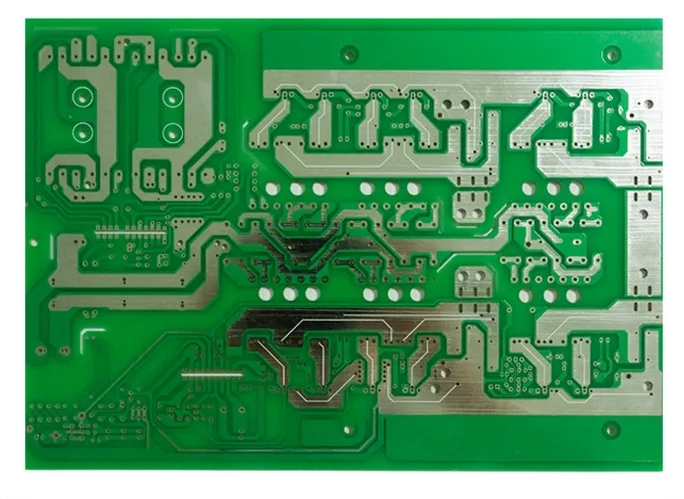
6、 Multilayer circuit board (high frequency board) wiring
High frequency circuits tend to have high integration and high wiring density. Selecting multilayer circuit boards (high frequency boards) is not only necessary for wiring, but also an effective means to reduce disturbance. In the PCBLAYOUT stage, reasonable selection of a certain number of layers of high-frequency boards (microwave RF boards) can significantly reduce the size of printed circuit boards, make full use of the intermediate layer to set shielding, better complete the nearby grounding, effectively reduce parasitic inductance and shorten the transmission length of signals, and together can significantly reduce the cross disturbance between signals. All these methods are beneficial to the reliability of high-frequency circuits. Some data show that the noise of the 4-layer circuit board is 20dB lower than that of the double-sided circuit board in the same data. However, there is also a problem. The higher the number of PCB layers, the more disordered the manufacturing process, and the higher the unit cost. This requires us to select a proper number of PCB layers, as well as a reasonable layout plan of components and equipment, and select the correct wiring rules to complete the planning.
7、 The ground wire of high-frequency digital signal is separated from the ground wire of analog signal
When the analog ground wire, digital ground wire, etc. are connected to the public ground wire, they shall be connected with high-frequency choke magnetic beads or directly blocked and appropriate local single point interconnection shall be selected. The ground potential of high-frequency digital signal ground wire is generally inconsistent with that of analog ground wire, and there is often a certain voltage difference between the two. In addition, the ground wire of high-frequency digital signal often contains rich harmonic components of high-frequency signal. When directly connecting the digital signal ground wire and analog signal ground wire, the harmonic of high-frequency signal will disturb the analog signal through the ground wire coupling method. Therefore, in general, the ground wire of high-frequency digital signal and the ground wire of analog signal should be isolated, and the method of single point interconnection at a suitable location or the method of high-frequency choke magnetic bead interconnection can be selected.
Influence of High Frequency Board (Microwave RF Board) Equipment
If the high frequency board (microwave RF board) is not well planned, it will lead to line disorder between periods, directly affect the transmission speed, and even cause the high frequency board (microwave RF board) to fail the test. Therefore, you need to pay attention to the typesetting skills when making high-frequency boards (microwave RF boards). PCB manufacturing, PCB design and PCBA processing manufacturers will explain the high frequency board/high-speed PCB manufacturing and layout skills.


Just upload Gerber files, BOM files and design files, and the KINGFORD team will provide a complete quotation within 24h.