
Professional PCB manufacturing and assembly
Building 6, Zone 3, Yuekang Road,Bao'an District, Shenzhen, China
+86-13410863085Mon.-Sat.08:00-20:00

Analysis of Two Reasons for FPC Breaking
To know these two reasons, we need to analyze the professional design of Cabol, leave enough space for hinge, and make sure that FPC is not too hard.

1. The FPC is too short.
2. The material is too hard. It may be better to replace it with a softer material. It is not a problem to fold it 100000 times.
Another point is that the fracture of the FPC is an initial problem, which I personally think is not very difficult. The most important thing is the FPC sound. To eliminate the interference between the FPC and the vias, what good methods do you have for FPC sound? There are several problems brought by FPC: the lcd does not display due to breakage and the flip sound is abnormal; For the fracture, the design length is too short. In addition, the design of the hole gap at the FPC is not reasonable, and the flip abnormal noise is often caused by the contact and scraping between the FPC and the shell wall. In short, the FPC can only be designed in place after repeated attempts. It is better to use a transparent shell, or cut the shell, observe more, and then make design improvements.
Of course, some manufacturers have no problem when they start to make samples in Hong Kong. Later, if there is a problem in mass production, we must see if it is a problem of materials
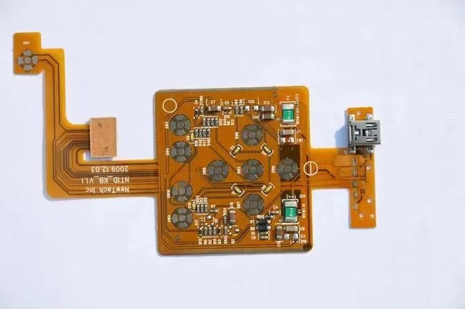
(1) First analyze the FPC picture of fracture, we can see that:
1. The fracture is the electromagnetic shielding layer of the outer layer of FPC
2. It can be seen from the figure that this layer is folded from the back of the product in the swing area, so it is judged that this layer is made separately and then pasted on the FPC product
(2) Speculation of fracture cause:
1. The shielding layer is solid copper with high hardness, which increases the possibility of fracture during swing.
2. The shielding layer is additionally bonded to the FPC, which is not closely integrated with the FPC product, and will deviate from the originally set bending direction during the swing process, which may lead to excessive stress concentration and fracture.
(Therefore, it is ruled out that the FPC material problem mentioned by lbmouse is the direct cause of fracture. In addition, there is no corresponding information on structural problems, so we will not discuss it temporarily.)
(3) Suggestion:
1. Wrap tape around the fracture and bind it to FPC to increase its tightness with FPC.
2. Change the copper surface of the shielding layer into a grid to reduce the hardness.
1. Long term suggestions:
For the shielding layer in the FPC swing area, use the production method of printing or coating conductor, or stick the conductive cloth dedicated to the electromagnetic shielding of FPC, which will completely avoid the problem of shielding fracture, and will not increase the cost.
The above is my personal suggestion. I wonder if you have any suggestions.
FPC can design a tear resistant wire, and Korean mobile phones have tear resistant wires. Last time our mobile phones were converted to domestic production, the domestic manufacturers began to have problems. Later, they added tear lines, but there was no problem at all. Also, DOME is wrapped with a protective film to prevent moisture and dust!
It should be possible to change the copper layer of the FPC to a copper network and increase the deflection of the FPC. However, it is suggested that binding should be done as a last resort. I personally think that the fracture in this drawing is caused by pulling, that is, the FPC is too short, and that is, the FPC vias, mainly the mechanism of the rubber shell. Now we have used silver paste printing, which can make the FPC thinner, and the effect is also good, 100000 times ok!]
Refer to the bending of the mobile phone motherboard for the hollow structure.
This is caused by torsional tension during overturning. The FPC at (right) B-B in the figure should be moved to the middle to lengthen the length of torsional deformation to reduce the possibility of fracture.
There are many useful aluminum foils for FPC shielding, and the flip will be better;
In the design of FPC, I think the most important thing is to reduce stress concentration. The fillet must be as large as possible. In many cases, the inner fillet of FPC breaks. Increasing the fillet will improve greatly, and there should be no obvious stress on both ends of the shaft (as someone said earlier, the connector should not be too close to the leading out part of the shaft, and the adhesive layer on both ends of FPC will produce great torque);
The FPC also has its own torque. If the axial length of the over axis part is longer, its own torque will be weakened, but if it is too long, there will be obvious slapping sound between layers;
The supplier of FPC is also an important link. There are electrolytic copper and calendered copper on the FPC copper wire. The service life of electrolytic copper is relatively low, which may affect the test;
The length simulation of FPC is very important, and the analysis of failed components in the later stage should be done in one step.
In fact, the life of FPC is also related to the casing structure. Because it is often necessary to move, and the space inside the housing is limited, FPC will inevitably contact with the hard housing. The flip is not so obvious, but the flip is not.
Quality and price are inseparable. However, the single value of FPC is relatively low, but its onboard original components are not cheap. In addition, if the FPC is damaged during the warranty period, the warranty cost is much higher than the value of FPC
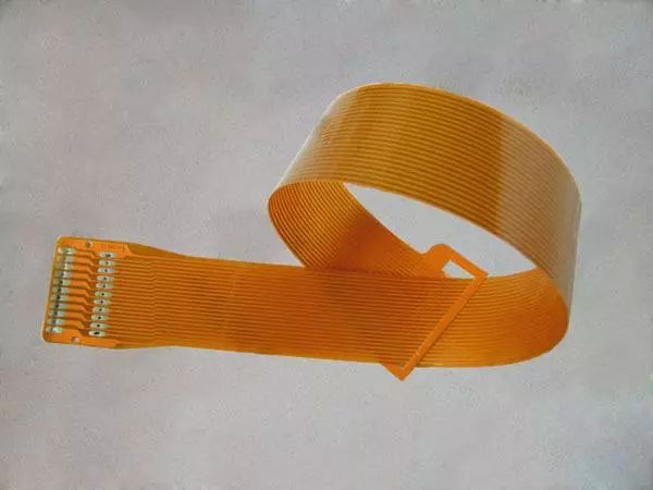
Describe FPC connectors
Oct 29,2022


Just upload Gerber files, BOM files and design files, and the KINGFORD team will provide a complete quotation within 24h.