
Professional PCB manufacturing and assembly
Building 6, Zone 3, Yuekang Road,Bao'an District, Shenzhen, China
+86-13410863085Mon.-Sat.08:00-20:00

The purpose of this test is to verify the resistance to electrostatic discharge (ESD) caused by the proximity or contact of objects, people or devices. The internal of objects or people can accumulate electrostatic charges with a voltage higher than 15kv. Experience shows that many failures and damages with unknown causes are likely to be caused by ESD. The ESD activity is obtained by discharging the ESD simulator to the surface of and near the EUT, and testing the instrument (EUT). The severity level of discharge is clearly defined in the product standard and EMC test plan prepared by the manufacturer. The EUT checks for functional faults or disturbances in all its operating modes. The pass/fail criteria must be defined in the EMC test plan and determined by the manufacturer of the product.
Anti transient conductivity of PCB
The purpose of this test is to verify the resistance of EUT to transient short duration impact with fast rise time that may be generated by inductive load or contactor. The fast rise time and repetitive nature of the test pulse cause these spikes to easily penetrate the circuit of the EUT and may interfere with the operation of the EUT. The transient directly affects the permittivity of the total power supply and signal lines. In other immunity tests, the configuration of general operation shall be used to monitor EUT according to pass/fail criteria.
Anti electromagnetic radiation of PCB
The purpose of this test is to verify the anti-interference capability of the product against PCBs of radios, radio transceivers, mobile GSM/AMPS phones, and various electromagnetic fields generated from industrial electromagnetic sources. If the system is not shielded, the electromagnetic field radiation can be coupled on the interface cable and enter the circuit through the conduction path; Or it can directly couple the wiring of printed PCB circuit. When the amplitude of RF electromagnetic field is large enough, the induced voltage and demodulation carrier wave can affect the normal operation of the device.
The run of PCB radiation resistance test is usually the longest and most difficult, requiring very expensive instruments and considerable experience. Compared with other PCB immunity tests, the success/failure criteria defined by the manufacturer and the written test plan must be sent to the test room. When sending EUT into radiation field, EUT must be set in normal operation and the most sensitive mode.
When the EUT is exposed to a graded interference field whose frequency exceeds the required frequency range of 80MHz to 1GHz, normal operation must be established in the test room. Some PCB anti-interference standards start from 27MHz. Severity level This standard usually requires a PCB immunity level of 1V/m, 3V/m or 10V/m. However, equipment specifications may have their own requirements on specific "problem (interference) frequencies". It is the interest of PCB manufacturers to determine the proper radiation resistance level of PCB products.
IEC/EN61000-4-3 is referenced in the new PCB immunity standard EN50082-1:1997 for unified field requirements. IEC/EN61000-4-3 requires a unified test environment based on test samples. The test environment is realized in an echo free room with tiles arranged by ferrite absorbers. The ferrite tiles are used to block reflection and resonance so as to establish a unified test site in the room. This overcomes the sudden and frequent unrepeatable test errors caused by reflection and field gradient in traditional unlined rooms. (The semi anechoic room is also an ideal environment for measuring the radiation emission of the indoor abnormal environment that requires precision).
For semi anechoic rooms, RF absorbers shall be arranged on the walls and ceilings of the semi anechoic rooms. Mechanical and RF design specifications shall be suitable for heavy ferrite bricks arranged on the roof of the room. Ferrite bricks are placed on the dielectric material and attached to the top of the room. In the room without lining, the reflection of metal surface will lead to resonance and standing wave, which will produce wave peaks and troughs on the strength of the test space. The field gradient in a typical unlined room can reach 20 to 40 dB, and this will lead to sudden failure of the test sample in a very low field. Room resonance causes low test repeatability and high probability of "over testing". (This may lead to over design of products) The new PCB anti-interference standard IEC1000-4-3 with the same requirements on site makes up for these serious defects.
The hardware and software of the generated test site require that a high-power broadband RF amplifier be used to drive a broadband transmitting antenna with a frequency range of more than 26MHz to 2GHz. This antenna is 3 meters away from the tested equipment. Under the control of software, fully automatic testing and calibration can achieve the best operation, providing greater flexibility for testing and full control of all key parameters, such as scanning rate, frequency pause time, modulation and field strength. Software hooks allow synchronization of monitoring and functional stimulation of EUT. Interactive function is required in the actual test to realize the real-time change of EMC test software and EUT parameters. This user access feature allows rapid recording of all data for effective evaluation and distribution of EUT's EMC performance.
Pyramid Absorber The traditional pyramid (cone) absorber is effective, but the huge size of the pyramid makes it impossible to test the small available space in the room. For the lower frequency of 80MHz, the length of the pyramid absorber should be 100cm. To operate the lower frequency of 26MHz, the length of the pyramid absorber should exceed 2m. Pyramid absorbers also have disadvantages, they are fragile, easy to be destroyed due to collision, and flammable. It is also impractical to use these absorbers on the floor of the room. Because of the heat of the pyramid absorber, a field strength greater than 200V/m will cause a high risk of fire if it lasts for more than a period of time.
Ferrite tile absorber
Ferrite tiles are space efficient, but they add significant weight on the roof, walls and doors of the room, so the mechanical structure of the room becomes very important. They can work effectively at low frequencies, but when the frequency is higher than 1GHz, their work becomes relatively inefficient. Ferrite tile is very dense (100mm × 100mm × 6mm thick) and can withstand the field strength exceeding 1000V/m without fire hazard.
Difficulties in PCB radiation resistance test Because the auxiliary equipment used to operate the EUT provides stimulus signals to monitor its own performance, it must be PCB interference resistant to this sensitive field, which is an inherent difficulty in running radiation sensitivity test. This often leads to many difficulties, especially when the auxiliary equipment is relatively complex, which requires many cables and interfaces connected to the EUT that are perforated and run through the shielded test room. All cables passing through the test room must be shielded, and/or filtered to make the test field shield them, so as to avoid reducing the shielding performance of the test room. The compromise of the shielding performance of the test room will cause the unintentional leakage of the test field into the surrounding environment, which may cause interference to users of the spectrum. RF filters using PCB data or signal lines are not always feasible, such as when there is a lot of data or high-speed data links are used.

Classification of FPC multilayer soft board
Oct 29,2022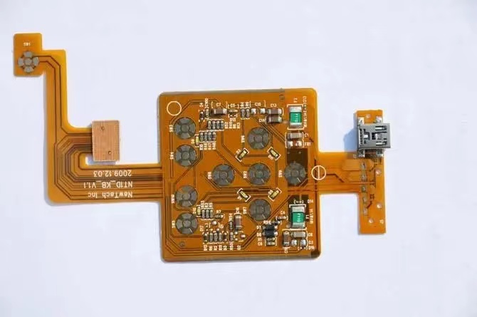


Just upload Gerber files, BOM files and design files, and the KINGFORD team will provide a complete quotation within 24h.