
Professional PCB manufacturing and assembly
Building 6, Zone 3, Yuekang Road,Bao'an District, Shenzhen, China
+86-13410863085Mon.-Sat.08:00-20:00

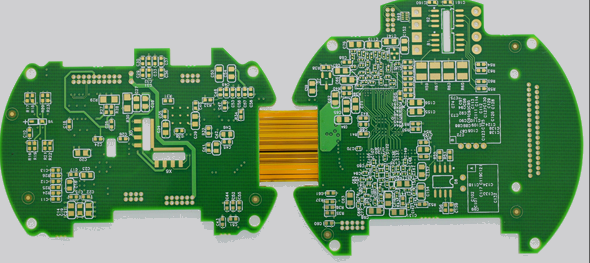
A typical rigid-flex-pcbs has two groups of hard covers made on the upper and lower surfaces of the circuit board, between which one or more layers of FPC are sandwiched in the middle. Generally speaking, the cover area of the rigid-flex-pcbs is kept without lines. The cover plate and FPC will be firmly attached together and extended to the hard area, that is, the part containing PTH. The soft layers may be attached to or separated from each other in the area requiring softness. The selection depends on the relative deflection demand or manufacturing cost.

How to define the rigid-flex-pcbs
Most of the cover plates will not be made into multi-layer structures in advance, but will be made into standard single-sided line double copper panels, which are constructed by pressing copper sheets or cover plates during multi-layer pressing. The copper sheet pressing method consists of using a layer of film with a piece of copper sheet above to construct the external surface of the soft and hard bonding plate. The cover plate pressing process is similar to the general pressing process, but the original copper layer is replaced by the circuit board substrate with one side full of copper. Both processes can be used in the traditional double copper cover plate process to deal with the soft and hard bonding plate process with odd layers or other structures.
Before the FPC stack is pressed, the cover plate, each part of the soft plate, the film or the connecting adhesive will be punched, windowed, grooved and partially formed to produce the non adhering area or contour edge. These parts are difficult to deal with in the final soft and hard plates.
The windowing part is made of a knife mold, which is aligned with the adhesive or film layer by the tool hole and the pin, and precisely cuts out the specific area. The same process is also used to produce filler materials, which have the same thickness as the adhesive, such as Teflon, Tedlar or TFE glass cloth. However, at present, most of the processes used by the operators do not add fillers to save manpower, but in the pressing process, they will face the problems of fracture in the fault zone, gradual thinning and tilting at the junction, and inability to fully control the film flow. The filler is the area extending into the window when stacking, and its functions are:
1: Restore the thickness of the stack to achieve a uniform compression pressure
2: Avoid FPC interlayer bonding
3: Lock the flow of adhesive (or film)
4: Keep distortion to a minimum
The cover plate will be grooved in advance along the edge of the area to be exposed by the FPC. If the cover plate is not grooved before pressing (or nicked inside for disconnection), the end product cutting this edge requires a very special and accurate Z-axis control to avoid damaging the FPC.
The edge of FPC layer may not be attached to other parts in the final product, so it is very difficult to cut lines. Most of these parts will be partially cut with a knife mold in advance. Before pressing, the scrap will not be reported clearly, and nothing will be cleared. The FPC layer will enter the manufacturing process as a whole. The tool system in the edge and leftover area will be used to assist in alignment and thickness control.
If it is necessary to generate multi segment structure in PTH area, sequential pressing process must be used. With this technology, the layers of those thin areas will be completed and PTH processed first, and then imported into the final rigid-flex-pcbs stack. At this time, the area where PTH has been completed is sealed inside the thick soft and hard plates with additional soft and cover layers to establish the final thickness for the second PTH process.
If the part not attached to the hard area is too large, it may expand during plasma treatment and cause layer separation, which must depend on the overall sealing and the amount of free substances contained. When the FPC bending area exceeds 4-5 square inches, the expansion force will be generated in the hot and vacuum plasma process, which may pull the edge of the cover plate. In the face of this situation, sometimes we can make an exhaust hole to release pressure in these areas, which may open the edge of the cover plate. In this case, sometimes we can make vent holes to release pressure in these areas, but we must seal them before PTH process.
The soft and hard bonding plates need particularly strict quality control. Perhaps the most challenging inspection procedure is thermal stress, and it may be necessary to conduct visual cutting and section analysis of representative PTH test pieces. The test piece shall be baked at 125 ℃ for at least 6 hours, then cooled, fluxed and tin bleached at 288 ℃ for 10 seconds. After that, check the defects of the surface, such as abnormal braided fibers, fiber exposure, scratches, annular separation, dents, and indentation, and then make slices to analyze the overall condition of electroplating and the broad characteristics of soft and hard areas.
It is a common practice to first check the pad and line area adjacent to the PTH hole, and then check the position where the next PTH hole extends along the line. A common quality problem of soft and hard boards that causes delamination is the substrate voids in the extended area. These are voids or bubbles in the dielectric structure. It is generally defined that as long as the substrate voids are larger than 3mil or interfere with the space between conductors, they will be evicted.
Some applications require very serious bending in the soft plate area, and the gradual design will be used to reduce the stress in the assembly state (but it must go through a rather complex process and high stress welding assembly). Progression is a design technology used in FPC layer. The sequence of bending in the bending area is from inside to outside. At this time, it will gradually increase to compensate for the increased channel length.
Soft and hard combination plate and welding
Oct 28,2022


Just upload Gerber files, BOM files and design files, and the KINGFORD team will provide a complete quotation within 24h.