
Professional PCB manufacturing and assembly
Building 6, Zone 3, Yuekang Road,Bao'an District, Shenzhen, China
+86-13410863085Mon.-Sat.08:00-20:00

Protel, a circuit aided design system from Altium, is the first board level design system to integrate all design tools into one. On the basis of the completed schematic diagram, PCB design using Protel should generally follow the steps of determining the shape, layout, wiring, rule check and so on. This paper analyzes the basic principles of layout and wiring, and discusses some experiences and skills in the whole process of PCB design.
With the popularity of computer, electronic CAD technology is not only a high-level professional design of large-scale integrated circuit special tools, especially the appearance of Protel software, so that the general engineering and technical personnel can also use it to deal with the circuit design problems in daily work, improve work efficiency. Protel is the most convenient to use, the fastest to operate, the best humanized interface auxiliary tool in the circuit aided design (EDA) industry at present, and also the most used EDA tool in China. This paper takes Protel99 SE as a design tool to analyze and discuss the basic principles and experience skills in PCB design.
First, quickly determine the PCB shape
Design PCB first to determine the shape of the circuit board, usually in the forbidden wiring layer to draw the electrical wiring range. Unless there are special requirements, the general shape of the circuit board is rectangular, the aspect ratio is generally 3:2 or 4:3 is more ideal. Before drawing, you can draw two horizontal and two vertical lines at will, and then use the "Set Origin" tool in the "Place Toolbar" to set the endpoint of a certain line segment as the origin, that is, the coordinate is (0,0), and then double click each line segment to make corresponding changes to the coordinate values of its starting point and ending point, so that the four line segments meet end to end, forming a closed rectangular box. The shape of the circuit board is determined. If you need to adjust the size of the circuit board during the drawing process, just modify the corresponding coordinate values of each line segment. Considering the cost, length of copper wire and anti-noise ability, the smaller the circuit board size, the better, but the board size is too small, the heat dissipation is bad, and the adjacent wire is easy to cause interference. However, when the size of the circuit board is greater than 200mm×150mm, the mechanical strength of the circuit board should be considered, and the fixed hole should be installed appropriately to play the role of support.
Two, component layout
Before starting the layout, we must first load the components through the network table. In this process, we often encounter the error that the network table cannot be completely loaded, which can be mainly classified into two categories: One is to find the component, the solution is to confirm the packaging form of the defined component in the schematic diagram, and confirm that the corresponding PCB component library has been added, if still can not find the component to build a component package; The other is the loss of pins, the most common is diode, transistor pin loss, this is because the pin in the schematic diagram is generally the letters A, K, E, B, C, and the pin of the PCB component is the number 1, 2, 3, the solution is to change the definition of the schematic diagram, or change the PCB component definition to make it consistent. Experienced designers will generally build their own PCB component library according to the actual component packaging shape, easy to use and not easy to make mistakes.

There are some basic rules that you must follow when you layout:
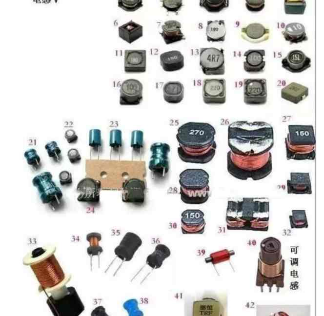
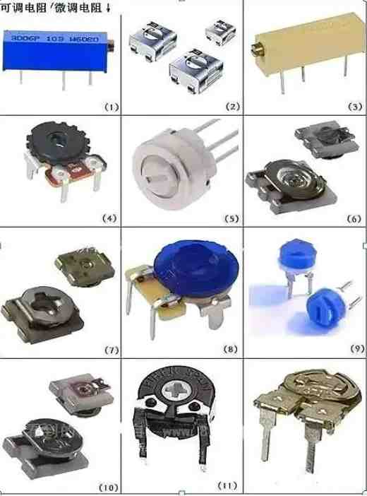
(1) Special consideration for special components. High-frequency components should be as close to each other as possible, the shorter the connection the better; Increase the distance between components with high potential difference as much as possible; Heavy components should be fixed with a support; The heating element should be far away from the heat sensitive element and install the corresponding heat sink or placed outside the plate; The layout of adjustable components such as potentiometer, adjustable inductance coil, variable capacitor and micro switch should consider the structural requirements of the whole machine, in order to facilitate adjustment. In short, some special components in the layout should be from the characteristics of the components themselves, the structure of the chassis, the convenience of maintenance and debugging and other aspects of comprehensive consideration, to ensure that a stable, easy to use PCB board.
(2) Layout according to circuit function. If there are no special requirements, as far as possible according to the schematic component arrangement of the component layout, usually the signal from the left input, the right output, input from the top, the bottom output. According to the circuit flow, arrange the position of each functional circuit unit, so that the signal flow is smoother and keep the direction of the same. In addition, the digital circuit part must be separated from the analog circuit part of the layout to reduce interference.
(3) text annotation of the screen printing layer. In order to facilitate the installation and maintenance of the circuit, it is generally necessary to print the required logo pattern and text code on the upper and lower surfaces of the printing board, such as component label and nominal value, component profile shape, manufacturer logo, etc. Many beginners often omit the design of the screen printing layer, or only pay attention to the neat and beautiful placement of text symbols, and after the actual production of PCB board, The characters on the board are either blocked by components or invade the welding aid area to be erased, and the component label is stamped on adjacent components, causing inconvenience in assembly and maintenance. The correct silk screen layer character layout principle should be no ambiguity, stitching, beautiful and generous.


Just upload Gerber files, BOM files and design files, and the KINGFORD team will provide a complete quotation within 24h.