
Professional PCB manufacturing and assembly
Building 6, Zone 3, Yuekang Road,Bao'an District, Shenzhen, China
+86-13410863085Mon.-Sat.08:00-20:00

1. Layout of components
Reasonable layout of PCB components is the basic premise for designing high-quality PCB drawings. Requirements for component layout mainly include installation, stress, heating, signal and aesthetics.
1.1. Installation
It refers to a series of basic requirements put forward in specific applications to install the circuit board into the chassis, shell and slot smoothly, avoid space interference, short circuit and other accidents, and make the designated connector in the designated position on the chassis or shell. I will not repeat it here.
1.2. Force
The circuit board shall be able to withstand various external forces and vibrations during installation and operation. For this reason, the circuit board should have a reasonable shape, and the positions of various holes (screw holes, special-shaped holes) on the board should be reasonably arranged. Generally, the distance between the hole and the plate edge shall be at least greater than the diameter of the hole. At the same time, it should be noted that the weakest section of the plate caused by profiled holes should also have sufficient bending strength. The connectors on the board that directly "extend" out of the equipment shell shall be reasonably fixed to ensure the reliability of long-term use.
1.3. Heating
For high-power devices with severe heat generation, in addition to ensuring heat dissipation conditions, attention should be paid to placing them in proper positions. Especially in the precise analog system, we should pay special attention to the adverse effects of the temperature field generated by these devices on the fragile preamplifier circuit. Generally, the part with very large power shall be made into a module separately, and certain thermal isolation measures shall be taken between it and the signal processing circuit.
1.4. Signal
Signal interference is the most important factor to be considered in PCB layout design. Several basic aspects are: weak signal circuit and strong signal circuit are separated or even isolated; The AC part is separated from the DC part; The high frequency part is separated from the low frequency part; Pay attention to the direction of PCB signal line; Layout of ground wire; Appropriate shielding, filtering and other measures. These have been repeatedly emphasized by a large number of scholars, and will not be repeated here.
1.5. Aesthetic
Not only the orderly placement of components, but also the graceful and smooth routing should be considered. Because ordinary laymen sometimes put more emphasis on the former to one-sided evaluate the advantages and disadvantages of circuit board design. For the image of PCB products, the former should be given priority when the performance requirements are not strict. However, in high-performance occasions, if you have to use double-sided boards, and the circuit board is also packaged in it, you should give priority to the aesthetics of wiring. The next section will specifically discuss the "aesthetics" of cabling.
2. Wiring principle
The following details the anti-interference measures that are not common in the literature. Considering that in practical applications, especially in the trial production of products, a large number of double-sided boards are still used, the following contents are mainly for double-sided boards.
2.1. Wiring "Aesthetics"
When turning, avoid right angles and try to use oblique lines or arcs for transition.
The routing shall be orderly and arranged in a centralized manner by category, which can not only avoid mutual interference of signals of different properties, but also facilitate inspection and modification. For digital systems, there is no need to worry about interference between signal lines (such as data lines and address lines) of the same camp, but control signals such as read, write, and clock should be independent and protected by ground wires.
When laying the ground in a large area (further discussed below), the ground wire (actually, it should be the ground "surface") and the signal wire should be kept at a reasonable and equal distance as far as possible, and should be as close as possible under the premise of preventing short circuit and electric leakage.
For weak current system, the ground wire and power line shall be as close as possible.
For the system using meter sticker components, the signal lines shall be all on the front as far as possible.
2.2. Ground wire layout
There are many discussions on the importance and layout principle of ground wire in the literature, but there is still a lack of detailed and accurate introduction on the ground wire layout in the actual PCB. My experience is that in order to improve the reliability of the system (rather than just making an experimental prototype), no matter how much emphasis is placed on the ground wire, especially in weak signal processing. To this end, we must spare no effort to implement the principle of "covering a large area of land".
When paving, it must generally be grid shaped, except for those scattered sites separated by other lines. The heating performance and high-frequency conductivity of the grid ground are much better than the whole ground wire. In double-sided board wiring, sometimes the ground wire has to be separated in order to run the signal line, which is extremely unfavorable for keeping the ground resistance low enough. Therefore, we must adopt a series of "smart" means to ensure the "smooth" of the ground current. These techniques include:
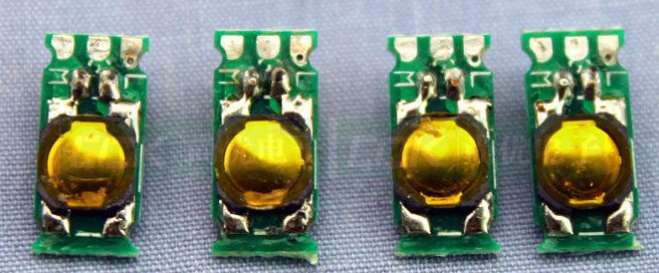
Surface mount components are widely used to eliminate the space occupied by welding holes that should belong to the ground wire.
Make full use of the front space: When surface mount components are widely used, try to make the signal wire go to the top layer as far as possible, and give the bottom layer to the ground wire "selflessly". This involves countless small tricks. There is a trick in my book One of PCB Skills: Swapping Pins, and many similar spells will be written in the future.
Reasonably arrange the signal lines, and give the important areas on the board, especially the "hinterland" (which is related to the communication of the whole board ground wire) to the ground wire. As long as carefully designed, this can be achieved.
Coordination between the front and the back: Sometimes the ground wire is "desperate" on one side of the board. At this time, try to make the wiring on both sides coordinate with each other. "There is no need to leave the master here, but there is a place to leave the master". A sufficient area is vacated at the corresponding position on the back to lay the ground wire, and then through the vias with sufficient number and reasonable location (considering the large resistance of the vias)? quot; The bridge "connects the two sides of the Taiwan Strait, which are forcibly divided by the signal lines passing across but are reluctant to give up and hope for reunification, into a whole with sufficient conductivity.".
How to jump over the wall in a hurry: When the huge ground wire is cut off by only one signal wire, let the signal feel a little aggrieved and take the jumper wire. Sometimes, I am not reconciled to just pulling a bare wire, and this signal happens to pass through a resistor or other "long leg" devices, so I can rightfully extend the pin of this device, so that it can also act as a jumper wire, which not only passes the signal, It also avoids the shameful name of jumper wire: - (Of course, in most cases, I can always let such signals pass through the right place to avoid crossing with the ground wire. The only thing I need is observation and imagination.
Minimum principle: the path of ground current should be reasonable, and large current and weak signal current should never go forward side by side. Sometimes, if a reasonable path is selected, the ground wire of a platoon is equal to that of a group army with unreasonable configuration.
Finally, by the way, there is a famous saying: "You can trust your mother, but never trust your land". In the case of extremely weak signal processing (below microvolt), even if the ground potential is consistent by any means, the ground potential difference at the key points on the PCB circuit will still exceed the amplitude of the signal being processed, at least by the same order of magnitude. Even if the static potential is appropriate, the instantaneous potential difference may still be large. For such occasions, first of all, make the circuit work as independent of the ground potential as possible in principle.
Describe the design principles of SMT and PCB
Jan 02,2023


Just upload Gerber files, BOM files and design files, and the KINGFORD team will provide a complete quotation within 24h.