
Professional PCB manufacturing and assembly
Building 6, Zone 3, Yuekang Road,Bao'an District, Shenzhen, China
+86-13410863085Mon.-Sat.08:00-20:00

PCB component placement error and placement defect detection
Wouldn't it be great if every printed circuit board we laid out had enough space to distribute components and leave enough space for wiring, through holes and text? I'm afraid we should dare to dream. The fact is that most of the circuit boards we design will try to contain as many circuits and functions as possible. Our job is to find a way to make it suitable for the circuit board while complying with all applicable design rules and constraints.
Because PCB space is very valuable, some subtle details will be missed during component placement, which may lead to problems in the manufacturing process, which is not unheard of. Sometimes, these difficulties will arise from the component footprint that we use even before we start placing components. Let's carefully study all these problems. First, some more common problems are caused by incorrect pin data or incorrect placement of components on the circuit board. Then, we will study some methods that can help enhance the detection ability of PCB component placement defects during PCB layout.
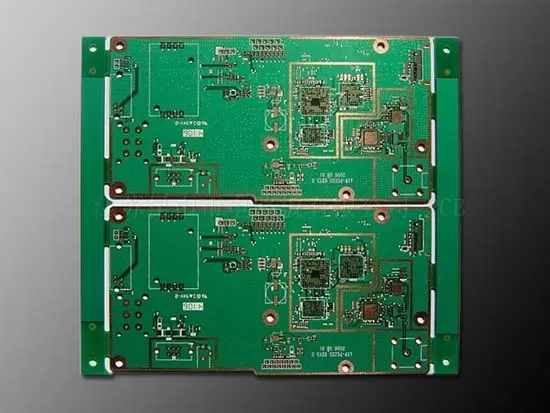
PCB assembly dimension drawing: not only CAD representation
Component defect detection starts with the correct CAD placeholder model
Many problems that make PCB manufacturing slow or even stop are caused by incorrect component occupancy model in PCB design CAD system. Many years ago, due to the large size of the parts and less strict design rules, designers could get rid of the problem of large space occupation. However, today, the same lack of attention to details will eventually lead to many problems. The following are some problems that may occur when component encapsulation is not built correctly:
Insufficient clearance: If the component contour and pad pattern are not created properly, it may inadvertently cause clearance problems with adjacent components on the board. Too small a contour line may result in insufficient space to place adjacent parts.
Poor solder joints: incorrect position and size of surface mount pads will lead to welding problems. If there is not enough space on the pad to place the leader, the solder legs may not be formed correctly, or if there is too much space, the component may "float". Through hole pins may be difficult to insert into holes that are too small, or if the holes are too large, they may be difficult to fix on the solder joints.
Functional issue: If the pad shapes welded to the plate are not numbered correctly, the components assembled to the plate will not work. In some cases, this may even lead to catastrophic failure, such as fire.
Testing, debugging and rework problems: There is not enough space between components or pad graphics, and the technicians who test and rework the circuit board will not have enough space to complete the work.
These packaging models must be built correctly in the CAD system before the layout starts. Many PCB design CAD tools have built-in automatic tools to help create footprint areas, and designers should use them as much as possible.
Once the footprints of the components are confirmed to be correct, the parts can be placed on the board. However, if the components are not placed correctly, manufacturing problems may occur.
Problems caused by incorrect component placement
Although there are still some designs that scatter components during placement, most of the time you will try to find enough space to place all parts on the board. At the same time, you must also comply with the electrical performance of the circuit and DFM rules to ensure the manufacturability of the circuit board. If you do not follow these rules, your manufacturer may encounter the following problems during PCB assembly:
Violation of clearance regulations: placing parts too close may cause difficulties for automatic picking and placing of components on the board. Insufficient clearance will also damage the ability of the circuit board to pass the automatic test, and may cause problems to the technicians who must debug and reprocess the circuit board.
Wrong position: Placing components in the wrong position and rotation will cause problems with wave soldering equipment. Higher components will enter the wave crest in shorter components, which may cast a shadow on smaller components and prevent them from completely welding. Components must also be properly aligned so that their pad patterns are welded evenly. Higher parts at the bottom of the board may also be difficult to pass through the waves, requiring special fixtures or later manual assembly.
Construction problem: If the metal connecting two pads is unbalanced, the smaller two pin assembly passing through the solder reflow furnace may be affected by the "tombstone effect". Pads with higher metal content emit heat, causing the solder on the other pad to melt faster. This unbalanced melting will sometimes pull the parts down from the unmelted mat and erect them like tombstones.
Misplaced components can cause many other problems. These ranges range from being inaccessible to conflicts with other system objects, such as racks and system chassis. You can use some tools to help you detect these problems when the circuit board is still in the layout state. Next, we will check.
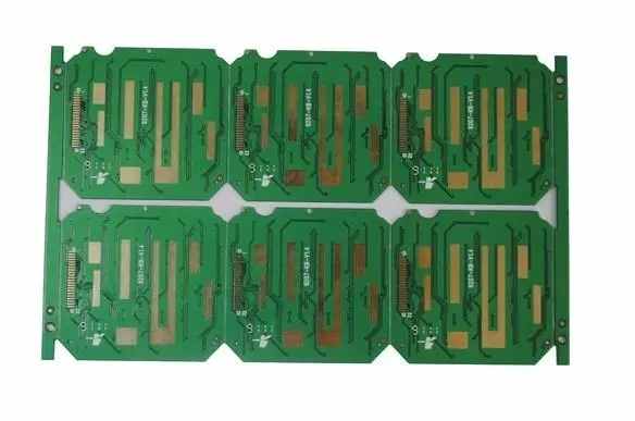
Careful placement of these parts is important to make the design manufacturable
PCB component placement defect detection method
To avoid problems with components that violate DFM rules, designers need to detect these problems in the layout before manufacturing the circuit board. The first line of defense against these errors is to use the design rule checking system built into PCB design CAD tools. These checks use the design rules and constraints you can set in the tool, and you can help yourself by setting as many rules as possible.
In modern PCB design CAD tools, you will be able to set rules and constraints for:
Element spacing
Component class to class spacing
Domain specific rules
Screen printing, solder mask and solder paste limitation
With these rules and constraints, you will be able to place your component packages on the board while automatically managing the minimum spacing requirements for manufacturability. In addition, most tools now have the ability to view and examine designs in 3D. By importing the mechanical properties of the board and other system boards and chassis, you can thoroughly check the design for errors. This includes checking components that are too close to other system functions, such as switches or connectors, or confirming that none of the higher electrolytic capacitors inadvertently pass through the system enclosure.
The key to the success of these PCB component placement defect detection methods is to ensure that they are fully utilized.
Take full advantage of your PCB design tools
The top half of PCB component placement defect detection is to ensure the correct construction of the package used in the design. First, make sure you use the latest information and diligently build the part according to its specifications.
The next step in preventing component placement defects is to set design rules and constraints using all the information needed to accurately place DRCs.
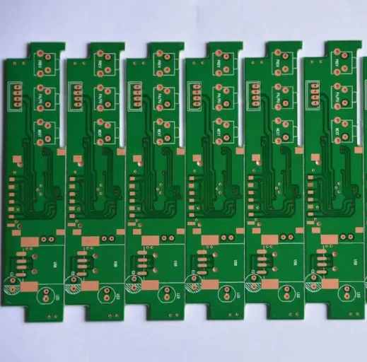
The rules and constraints of using PCB design CAD tools can help avoid component placement problems
These can be set for individual parts or part categories to manage the placement gaps required for design and manufacturing, thus helping you detect placement defects of PCB components. These values can be entered manually or imported from a set of saved rules and constraints. The circuit board assembly and the circuit board processing manufacturer explain the component placement error and the component placement defect detection method.


Just upload Gerber files, BOM files and design files, and the KINGFORD team will provide a complete quotation within 24h.