
Professional PCB manufacturing and assembly
Building 6, Zone 3, Yuekang Road,Bao'an District, Shenzhen, China
+86-13410863085Mon.-Sat.08:00-20:00

High frequency circuit is developing in the direction of high speed, low power consumption, small size and high anti-interference. First, introduce the high frequency PCB wiring, and second, introduce the high frequency circuit board layout. Now let's have a look.
With the rapid development of modern electronic industry, digital and high-frequency circuits are developing in the direction of high speed, low consumption, small size and high anti-interference, which puts forward higher requirements for the design of high-frequency circuit boards. Today, I will introduce the special countermeasures in the design of high-frequency circuit boards
1、 High frequency PCB wiring
The PCB system of Protel 99SE of high-frequency circuit can provide 32 signal layers, 16 mechanical layers, more than 70 working layers such as solder mask layer and solder paste layer for users to choose. Reasonable selection of layers can greatly reduce the size of PCB, effectively reduce the parasitic inductance, and effectively shorten the transmission length of signals, thus greatly reducing the cross interference between signals. All these are beneficial to the reliability of high-frequency circuit boards. According to experience, the noise of a four layer board is 20dB lower than that of a double-sided board for the same material. However, the higher the number of layers, the more complex the manufacturing process, and the higher the cost. High frequency circuits tend to have higher integration and higher wiring density.
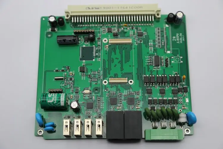
High frequency board
1. Wiring of power line and ground wire
The ground wire cannot form a current loop, so the power line and ground wire should be close to each other to minimize the enclosed area to reduce electromagnetic interference. In order to prevent local current from generating ground resistance interference in multi-level circuits, circuits at all levels shall be grounded at one point (or centralized grounding as far as possible). When the high-frequency circuit board reaches above 30 MHz, large area grounding shall be adopted. At this time, internal components at all levels shall also be grounded in a small area. Generally, during wiring, the wire width is between 12-80 mils, the power line is generally 20 mil-40 mil, and the ground wire is generally more than 40 mil. When possible, the wire should be as wide as possible.
2. General principles of high frequency circuit board wiring
The shorter the wire between the pins of high-frequency circuit devices, the better, and the less the bending, the better. The wire should preferably be straight. Sharp bending and sharp corners should be avoided as far as possible. If turning is needed, arc or broken line should be used for transition. This requirement is only used to improve the fixation strength of steel foil in low-frequency circuit, while meeting this requirement in high-frequency circuit can reduce the external transmission and mutual coupling of high-frequency signals. In the wiring of high-frequency circuit boards, it is better to take horizontal and vertical wiring alternately in adjacent layers. Parallel wiring in the same layer cannot be avoided, but ground wires can be laid in large areas on the back of PCB to reduce interference. For commonly used double-sided boards, multi-layer boards can use the middle power layer to achieve this function.
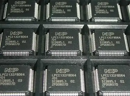
3. PCB wiring of integrated chip
A high frequency decoupling capacitor shall be set near each integrated circuit block. Because Protel 99SE software does not consider the position relationship between the decoupling capacitor and the decoupled integrated circuit when automatically placing components, allowing the software to place them makes them too far apart and the decoupling effect is not good. In this case, the two positions must be intervened in advance by manually moving components to make them close.
4. Copper-clad
The main purpose of copper coating is to improve the anti-interference ability of the circuit, while it is very beneficial to the heat dissipation and strength of PCB. Copper grounding can also play a role of shielding. However, large-area strip copper foil cannot be used because it will generate large heat when PCB is used for too long. At this time, strip copper foil is easy to expand and fall off. Therefore, it is better to use grid copper foil when copper is applied, and connect the grid with the grounding network of the circuit, so that the grid will have a better shielding effect. The size of the grid depends on the interference frequency of the key shielding.
2、 High frequency circuit board layout
Layout operation is very important in the whole PCB design. Layout is the basis of routing operation. To achieve a perfect component layout, designers need to consider the component layout from the perspective of circuit working characteristics and routing.
Protel 99SE has the function of automatic layout, which has two functions: clustered layout and statistical layout. However, it cannot fully meet the working requirements of high-frequency circuits. Designers also need to consider the layout comprehensively from the aspects of PCB manufacturability, mechanical structure, heat dissipation, EMI (electromagnetic interference), reliability, signal integrity, etc. Only in this way can the life, stability, EMC (electromagnetic compatibility) of PCB be effectively improved, To make the layout more perfect.
For the layout of high-frequency circuit boards, the designer should first consider the layout of the components that closely match the structure and have fixed positions (such as power sockets, indicators, connectors, switches, etc.), then the layout of special components on the circuit (such as heating elements, transformers, chips, etc.), and finally the layout of some small components. At the same time, the wiring requirements shall be taken into account. The placement of high-frequency components shall be as compact as possible, so that the wiring of signal lines can be as short as possible, so as to reduce the cross interference of signal lines as much as possible.
1. Mechanical structure
Power sockets, indicators, connectors and switches are all such components, which are positioning plug-ins related to mechanical dimensions. Generally, the interface between power supply and PCB is placed at the edge of PCB, and the distance from the edge of PCB is generally not less than 2mm; The indicating LED shall be placed accurately as required; Switches and some micro adjustment components, such as adjustable inductors and resistors, shall be placed near the edge of PCB for easy adjustment and connection; The components that need to be replaced frequently must be placed at the position where there are few components, so that they can be replaced easily. Components with a mass of more than 15g should be fixed with a bracket, and large and heavy components should not be directly placed on the PCB.
2. Heat dissipation
High power tubes, transformers, rectifier tubes and other heating devices generate more heat when working at high frequency. Ventilation and heat dissipation should be fully considered when arranging high frequency circuit boards. These components should be placed at the edge of PCB or at a ventilated place. The heating elements should be placed on the upper part of the board when the board is placed vertically. The heating elements should not be placed on the bottom of the double-sided board. The high-power rectifier tube and regulating tube shall be equipped with radiator and kept away from the transformer. Thermal components such as electrolytic capacitors should also be kept away from heating devices, otherwise the electrolyte will be dried, causing its resistance to increase and its performance to deteriorate, affecting the stability of the circuit
3. Layout of special components
Because the PCB power supply will generate 50Hz leakage magnetic field inside, when it is connected with some parts of the low-frequency amplifier, it will interfere with the low-frequency amplifier. Therefore, they must be isolated or shielded.
It is better to arrange all levels of the amplifier in a straight line according to the schematic diagram. The advantage of this arrangement is that the grounding current at all levels will flow in this stage without affecting the operation of other circuits. The input stage and output stage shall be as far away as possible to reduce parasitic coupling interference between them. Considering the signal transmission relationship between functional circuits of each unit, low-frequency circuit and high-frequency circuit shall be separated, and analog circuit and digital circuit shall be separated. The integrated circuit shall be placed in the center of the PCB, so as to facilitate the wiring connection between each pin and other devices.
Inductors, transformers and other devices have magnetic coupling, and they should be placed orthogonal to each other to reduce magnetic coupling. In addition, they all have strong magnetic fields, and there should be appropriate large space or magnetic shielding around them to reduce the impact on other circuits.
4. Electromagnetic interference
The methods we commonly use to eliminate electromagnetic interference include reducing the loop, filtering, shielding, minimizing the speed of high-frequency devices, and increasing the dielectric constant of PCB.
For example, the decoupling capacitor of integrated circuit shall be placed as close as possible. Generally, 0.1uF capacitor shall be used for the working frequency below 10MHz, and 0.01uF capacitor shall be used for the working frequency above 10MHz.
If there is a high potential difference between some components or wires, the distance should be increased to avoid discharge. High voltage components shall be arranged at places where it is not easy to reach during commissioning. PCB components that are easy to interfere with each other shall not be too close. Input and output components shall be as far away as possible to avoid feedback interference. In order to reduce the distribution parameters of high-frequency components, general circuits (low-frequency circuits) should be arranged in a regular manner to facilitate PCB assembly and welding.


Just upload Gerber files, BOM files and design files, and the KINGFORD team will provide a complete quotation within 24h.