
Professional PCB manufacturing and assembly
Building 6, Zone 3, Yuekang Road,Bao'an District, Shenzhen, China
+86-13410863085Mon.-Sat.08:00-20:00

Filtering function: in the power circuit, the rectifier PCB circuit turns AC into pulsating DC, and a large capacity electrolytic capacitor is connected after the rectifier circuit, making use of its charge discharge characteristics (energy storage function) to change the pulsating DC voltage after rectification into a phase contrast
Filtering function: in the power circuit, the rectifier circuit turns AC into pulsating DC, and a large capacity electrolytic capacitor is connected after the rectifier circuit, making use of its charge discharge characteristics (energy storage) to make the pulsating DC voltage after rectification become relatively stable DC voltage. In practice, in order to prevent the power supply voltage of each part of the PCB manufacturing circuit from changing due to load changes, the output end of the power supply and the power input end of the load are generally connected with tens to hundreds of micro farads of electrolytic capacitors. Since large capacity electrolytic capacitors generally have a certain inductance, which cannot effectively filter high-frequency and pulse interference signals, a capacitor with a capacity of 0.001 to -0.lpF is connected in parallel at both ends to filter high-frequency and pulse interference.
2. Coupling: In the process of low-frequency signal transmission and amplification, capacitance coupling is often used to prevent the interaction between the static working points of the front and rear circuits. In order to prevent excessive loss of low-frequency components in the signal, electrolytic capacitors with large capacity are generally used.
Next, we need to know the judgment method of electrolytic capacitor
Common faults of electrolytic capacitors include capacity reduction, capacity disappearance, breakdown short circuit and electric leakage. The capacity change is caused by the gradual drying of the electrolyte inside the electrolytic capacitors during use or placement, while breakdown and electric leakage are generally caused by excessive applied voltage or poor quality. Generally, the resistance of multimeter is used to judge the capacitance of PCB proofing power supply. The specific method is: short circuit the two pins of the capacitor to discharge, and connect the black probe of the multimeter to the positive pole of the electrolytic capacitor. The red stylus is connected to the negative pole (for pointer multimeter, the stylus is intermodulated when measuring with digital multimeter). Normally, the stylus should swing in the direction of low PCB resistance, and then gradually return to infinity. The greater the swing amplitude or the slower the return speed of the watch needle, the greater the capacity of the capacitance; otherwise, the smaller the capacity of the capacitance. If the pointer does not change at some place in the middle, it indicates that the capacitor is leaking. If the indicated resistance value is very small or zero, it indicates that the capacitor has been broken down and short circuited. Because the battery voltage used by the multimeter is generally very low, it is more accurate to measure the capacitance with low withstand voltage. When the withstand voltage of the capacitance is high, although the measurement is normal, leakage or breakdown may occur when high voltage is applied.
More attention should be paid to the use of electrolytic capacitors
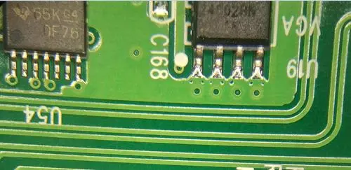
1. As electrolytic capacitors have positive and negative polarity, they cannot be connected reversely when used in the circuit. In the power circuit, the positive pole of the electrolytic capacitor is connected to the power output terminal and the negative pole is grounded when the positive voltage is output. When the negative voltage is output, the negative pole is connected to the output terminal and the positive pole is grounded.
When the polarity of the filter capacitor in the power circuit is reversed, the filtering effect of the capacitor is greatly reduced. On the one hand, it causes the output voltage of the power supply to fluctuate; on the other hand, it causes the electrolytic capacitor, which is equivalent to a resistor at this time, to heat up due to reverse energization. When the reverse voltage exceeds a certain value, the reverse leakage resistance of the capacitor will become very small. In this way, the capacitor will be cracked and damaged due to overheating soon after power on.
2. The voltage applied to both ends of the electrolytic capacitor shall not exceed its allowable working voltage. When designing the actual circuit on the PCB, a certain margin shall be reserved according to the specific situation. When designing the filter capacitor of the stabilized voltage power supply, if the rectifier voltage of the transformer secondary can reach 22V when the AC power supply voltage is 220~, the electrolytic capacitor with a withstand voltage of 25V can generally meet the requirements for PCB proofing. However, if the AC power supply voltage fluctuates greatly and may rise to more than 250V, it is better to choose electrolytic capacitors with withstand voltage of more than 30V.
3. The electrolytic capacitor shall not be close to the high-power heating PCB components in the circuit to prevent the electrolyte from drying up due to heating.
4. For the filtering of signals with positive and negative polarity, two electrolytic capacitors in series with the same polarity can be used as a non-polar capacitor.
5. Capacitor shell, auxiliary lead out terminal, positive and negative pole and circuit board must be completely isolated.
EMC design in PCB design circuit
Dec 03,2022


Just upload Gerber files, BOM files and design files, and the KINGFORD team will provide a complete quotation within 24h.