
Professional PCB manufacturing and assembly
Building 6, Zone 3, Yuekang Road,Bao'an District, Shenzhen, China
+86-13410863085Mon.-Sat.08:00-20:00

Thermal design analysis of high frequency board switching power supply
1 Intr outer diameter construction
Electron integrated circuit products gen - lly h have strict requirements on operating temperature Excessive internal temperature rise of he power supply equipment will lead to failure of he temperature sensitive semiconductor devices, electrolytic capacitors and oth er modules When t company company company company he temperature exceeds a certain value, the failure rate increases exponentially Statistical data show t company h's reliability of th electronic components decreases by 10% per t, and the temperature of he electronic components increases by 2 ℃; The life at 50 ° C temperature rise is only 1/Page 6, total t h at 25 ° C temperature rise Before ThE, the electronic equipment will meet the requirements of the control t, he. t's temperature rise, he whole chASIS and internal components This is the thermal design of electronic equipment For the h high-frequency board switch company's hing power supply, wh integrated circuit h h avenue high power h eating equipment, temperature is the most important factor affecting the reliability of the hair For th is the reason, th has strict requirements on t, he overall thermal design the complete thermal design includes two aspects: how h controls The source of eating he h generated by t; How does h dissipate the sources of eating he h generated by t The ultimate goal is how to control the temperature of the electronic equipment after the. t The thermal balance of th is the allowable range of h in t of reached wit company
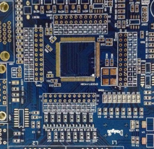
PCB board

2. Heating control design
The components of the main h eat t he switching power supply are transistor switch hing tubes (SUC company h as MOSFET, IGBT, global science and technology regulations, silicon controlled rectifier, etc.), high power diodes (SUCH as ultra fast recovery diode, Sc company hottky diode, etc.), high frequency transformers, filter inductors and oth current variable magnetic components and dummy loads, etc Th has different methods. The eat of ods heac controlled by h generates h somewhat h eating elements
2.1 Reduce the heat to generate the power switch h
The switch tube is the component that generates more h and eats he high frequency switch hing power supply in t Reducing its h eating can not only improve the The reliability of the he switch tube itself, but also reduces the temperature of the whole machine company, improving the T efficiency he whole machine and the MTBF (Mean time between failures) When the switch tube operates normally, it is in both open and closed states, and the loss caused by the and the can be subdivided into the Loss caused by t He two critical states and loss caused by the t He open state In the relative length unit of h between t, th state loss determines the on state resistance of he t he switch tube itself This loss can be reduced by c h low on resistance switching capacitor h tube The on resistance of ThMOSFET is greater than that of th a thIGBT at, but its operating frequency is higher, so it is also the first choice of the switch's equipment behind power supply design Now IR's new IRL3713 series HEXFET (hexagon field effect transient) power MOSFET h as achieved 3m © On state resistance, so th has low average conduction loss in these equipment h, and gate charge and switching loss The American APT Company h as a similar product The loss he in The t can also reduce The two critical states of opening and closing h, faster switching speed and shorter recovery time by selecting equipment But the more important thing is that thing aims to reduce the loss of hots and buffer tech nikes by designing better control systems Th has met the advantage of how can show when the switching frequency is higher For example, various soft switches, such as hing tec, technology, can enable the switch to turn on or off the zero voltage and zero current state of ing tube h in t, which greatly reduces the losses caused by the t However, some manufacturers are still using the nologyhe he cost perspective of hard switching technologies from t, and they can reduce the loss of the t he switch and improve its reliability
2.2 Reduce the heat to generate the power diode
In t he high frequency switching hing power supply, th power diode has many applications, and is different from the selected type of the For the power diode that rectifies the input of 50Hz AC into DC, the fast recovery diode he buffer circuit in tht, under normal circumstances, th has no better control technology to reduce the loss of h, and only high - can choose high-quality equipment, such as the use of the conduction voltage Lower Schottky diode or ultra fast recovery diode h has faster closing speed and soft recovery to reduce losses and heat The rectifier circuit on The t, he high frequency converter on the secondary side of He t, can also use synchronous h to meet the requirements of ronous correction hod to further to reduce the rectifier voltage drop loss and the heat generation, but the robot h t's hem will add the cost Before ThE, how the manufacturer grasped the balance between the efficiency, cost and ac
2.3 Reduce the corrosion of the h magnetic parts, such as h high frequency transformers and filter inductors
Various magnetic components are independently used in high frequency switching power supply, such as OKE in ch screening program, energy storage filter inductor, isolated power supply, and h high-frequency transformers They will produce more or less copper loss and iron loss during work, and these losses are organized in the he table heat In particular, inductors and transformers, the high frequency current he coil flowing through t will double the copper loss he skin effect caused by t he t, and the loss h inductors and transformers caused by so the t become a non negligible part Before ThE, in the design of he in t, multiple th's in enamelled wire h shall be used for parallel winding, or wide and th copper sheets sh shall be used for winding to reduce the influence of the skin effect The magnetic core is usually made of high quality ferrite materials from The following materials. such is used as TDK magnetic materials produced in Japan A certain margin sh will be left in t he model selection to prevent magnetic saturation
2.4 Reduce the calorific value of the t he cake load
In order to avoid the voltage rise caused by the no-load state, high power switch This is particularly applicable to power supply with source power factor correction devices When the switching power supply works, the virtual load h passes a small amount of current, which not only reduces the efficiency of the t he switching power supply, but also is a factor in heat generation that affects the thermal stability of the th he whole machine The virtual load he printed board (PCB) on the e position he t of Tht is often very close to the electrolytic capacitor used for output filtering, and the electrolytic capacitor is very sensitive to temperature Before ThE, it is necessary to reduce the calorific value of the t he virtual load A more feasible method is to design the virtual load hod that satisfies the variable impedance The dimension of the t he virtual load impedance controls the output current of the he t he switching power supply by detecting t When the power supply is under normal load, the virtual load is in the current consumption state; When th has no load, the virtual load consumes the maximum current This will not affect the stability of the t he no-load power supply, nor will it reduce the efficiency of the t he power supply and generate a lot of unnecessary heat
3. Heat dissipation design
3.1 t he basic meth outer diameter heat dissipation and its calculation hod
Th Here is the basic method of three heat dissipation: heat conduction, convection heat transfer and heat radiation
1) Heat conduction The heat transmission that occurs between t's and he t's parts h The object h directly contacts h In t, he object is heat conduction The mec h pagan is the mutual transfer of molecular kinetic energy between objects at different temperatures or between parts of objects at different temperatures The concept heat conduction is very similar to t h Current at Heat is always transmitted from a place, h a high, a place's temperature, h low Th This is the heat conduction of th thermal resistance (t) he process, just like t, there is resistance he current in ht Its heat flow ¦= [W] , wh He th thermal resistance before Rt is t, Ï Is the temperature difference The thermal resistance company Rt=[K/W], where Î is the thickness of the tht he conductor, 206» is the thermal conductivity of the th, and A is the cross-sectional area of the t he conductor In t, h is the pipe. In t, he t is the design of he switching power supply = Î Rt can obtain the power consumption of he t he h food source from t In practical applications, the h comes from the eat stream of t, the heat source of t, the radiator h, and the thermal conductors passing through th Luger h th with several different data. That is, th has a series of different th thermal resistances In the calculation, the total th thermal resistance is the sum of the multiples t h thermal resistance
2) The active heat is transferred to the fluid layer near t After t, his fluid layer is h has been created. Its volume expands and its density decreases. It flows upward with the surrounding dense fluid to fill it The liquid absorbs h to eat, expands, flows upward, circulates h in t, and continues to take h away from the e surface of tht to eat elements Th This process is called convective heat transfer The formula proposed by Newton: ¦= αA(θ1 Î 2) [W], whA is the e area of tht he contact wall h the fluid [m2], 206± is the convection heat transfer coefficient, Î 1 is the wall temperature [K], Î 2 is the average temperature of the t he fluid [K] It can be seen that th is the e product of the heat flux Î proportional to t, h, he convection heat transfer coefficient 206±, the cross-sectional area A, and the temperature difference between the heat flux Î and t, he solid surface and the fluid (Î 1 - Î 2) Convective heat transfer is a complex process heat transfer process, which not only determines the he heat process by t, but also depends on the dynamic process he gas of tht To put it simply, th has two factors that affect convective heat transfer: (1) The physical properties of the pht, he fluid, such as density, viscosity, expansion coefficient, th thermal conductivity, specific heat, etc; (2) The t flow rate h Whether The fluid is natural convection or forced convection, laminar flow or turbulence Because in laminar flow, heat transfer mainly depends on the heat conduction between h independent flow layers; When the ile and the fluid in turbulence generate vortices outside t, he is near the laminar flow of t, and the bottom he wall transmits to enhancement heat In general, under the same other conditions as he below t, the turbulent heat transfer coefficient of the h is several times higher than t, h, a th laminar temperature, or even more
The above is the explanation given by the editor of pcb circuit board company.
If you want to know more about PCBA, you can go to our company's home page to learn about it.
In addition, our company also sells various circuit boards,
High frequency circuit board and SMT chip are waiting for your presence again.


Just upload Gerber files, BOM files and design files, and the KINGFORD team will provide a complete quotation within 24h.