
Professional PCB manufacturing and assembly
Building 6, Zone 3, Yuekang Road,Bao'an District, Shenzhen, China
+86-13410863085Mon.-Sat.08:00-20:00

1. PCB analog circuit
For terminal products, analog circuits include all RF circuits, RF power supply, RF control circuits, digital to analog conversion circuits, and audio circuits. The above analog circuits are sensitive circuits, among which the sensitive circuits that need special attention include frequency terminal circuit (including local oscillator signal, power supply of frequency synthesizer circuit and control signal), receiving front-end circuit and audio circuit.
2. Interference source
Interference sources include all digital circuits, high-power RF circuits (power amplifiers, antennas and other high-power RF circuits). The interference sources that need special attention include clock circuit, switching power supply, high current power line, power amplifier circuit and antenna circuit. The interference of RF signals such as power amplifier and antenna is analyzed in this specification.
3. Interference way
For the mixed digital analog design, the interference channels that need to be concerned include: space radiation, power supply ground (plane or wiring), digital analog conversion circuits, and various control signals of analog circuits.
(1) Space radiation: circuits close to each other will generate crosstalk through radiation, which is the same as the concept of digital signal crosstalk. However, it should be noted that analog signals can tolerate far less crosstalk than digital signals, so it is necessary to control crosstalk at the layout stage. The way to reduce space radiation is generally to extend the distance of the layout and use shielding boxes.
(2) Power supply ground: the power supply ground is a circuit shared by digital and analog circuits, so the interference signal may be transmitted to the sensitive circuit through the power supply ground conductor. The way to control power supply ground crosstalk is to reasonably use filter devices and power supply ground separation.
(3) Digital to analog conversion circuit: it is an interface between analog and digital signals. If the layout or wiring is handled improperly, such as unclear layout partition and staggered routing of digital and analog circuits, crosstalk may be caused.
(4) Analog control signal: the ideal analog device should be that the control signal and analog circuit are isolated in the device, and the control signal can only ensure the correct logic level. However, devices often fail to do this, and the interference signal on the control signal may be directly coupled to the analog circuit. The solution is to reduce the interference to the control signal of analog circuit as much as possible, and use filter devices reasonably.
3、 Layout Rules for Digital Analog Mixed PCB Design
Rule 1: The simulator is arranged in the simulation area.
Rule 2: Digital devices are arranged in the digital area.
Rule 3: The digital analog hybrid chip is processed as a simulator and distributed in the analog area, but the digital interface needs to be close to the corresponding digital device layout.
Rule 4: The following circuits shall be protected with shielding boxes as far as possible
1. Receiving front-end circuit, including filter, LNA, impedance matching circuit, etc. between antenna and receiving chip.
2. Frequency source circuit: VCO, phase-locked loop chip, loop filter, crystal oscillator and other circuits. PCB
3. Power amplifier circuit. Different circuits shall have independent power supply paths as far as possible during layout
Rule 5: Place the filter capacitor before the power supply enters the analog area
Rule 6: Digital power supply and analog power supply are powered from different directions.
Rule 7: The power supply path in the same direction adopts the path from big signal to small signal for power supply.
The power supply path from large to small can reduce the interference of large signal circuit to small signal circuit.
Rule 8: The power supply wiring of the power amplifier should be as short as possible to reduce the voltage drop of the circuit.
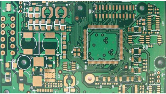
The battery connector of earlier mobile phones is generally designed in the middle of the mobile phone board, with RF circuit on the top and digital circuit below, as shown in the figure:
The advantage of this layout is that the RF and digital power supply paths are independent, and the power supply path of the attack amplifier is short.
Rule 9: When the power module is in PCB layout and PCB wiring, the heat dissipation copper area is reserved according to the power consumption.
Rule 10: PCB layout is to reserve space for grounding via for important pins.
The grounding pin of RF device needs to be grounded nearby and connected to the reference layer of RF signal. For example, if the second layer is hollowed, the grounding pin must be connected to the third layer nearby.
Rule 11: The filter capacitor is close to the pin of the power module, and the high-frequency filter capacitor is closer to the pin.


Just upload Gerber files, BOM files and design files, and the KINGFORD team will provide a complete quotation within 24h.