
Professional PCB manufacturing and assembly
Building 6, Zone 3, Yuekang Road,Bao'an District, Shenzhen, China
+86-13410863085Mon.-Sat.08:00-20:00

Programming of SMT production equipment and SMT mounter
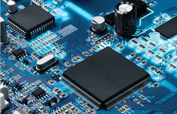
SMT machine is the key and complex equipment in SMT production smt placement machine has developed from early low-speed mechanical placement machine to high-speed optical centering placement machine, and has developed into multi-functional, flexible connection and modularization
1. Classification
1. It can be divided into medium speed mounter, high-speed mounter and ultra-high speed mounter according to speed.
2. Divided by function: high-speed/ultra-high speed mounters: mainly chip components, with few types of chip devices;
3. According to the degree of automation, it can be divided into automatic mounters: most mounters are of this type.
Second, the process flow of the precision placement machine
1. Place the circuit board with components as perpendicular to the bottom of the camera as possible on the tray.
2. Turn on the SMT switch
3. Put the circuit board and components together, and connect the original to the vacuum sucker.
4. Place the missing PCB to be welded on the tray as perpendicular to the bottom of the camera as possible.
5. Adjust the height knob of the vacuum suction pen to move it downward until it is 1-2CM from the PCB.
6. Turn on the display switch, and adjust the tray knob by observing the display, so that the pins of the IC chip completely overlap the corresponding pads of the PCB to be welded.
7. Place the IC chip vertically on the vacuum nozzle and gently place it on the corresponding pad of the printed circuit board.
8. Since the nozzle has not been powered off yet, the nozzle cannot be removed immediately. Please turn off the switch, stop the nozzle, and gently move the vacuum nozzle upward in the vertical direction to complete the installation.
Programming of SMT placement machine
The main task of the SMT machine is to accurately install various components on the PCB board, which is controlled by the computer and the vision system. The basic principle of placement is to pick up the parts from the feeder through the vacuum nozzle, calibrate and identify the shape and size of the equipment parts, and then install the parts according to the position coordinates set in the program. The whole installation process is completed by the corresponding computer controlled program. The main programs include:
1. Component position coordinate program (NC program)
Component outline dimension shape program (part program, supply program)
3. Sequence of components on placement machine (ARRAY program)
4. Substrate identification method (marker)
5. Contour coordinate size and positioning method of PCB program -- taking Panasonic model as an example
Main contents of each part of the program: PCB program:
It mainly includes: the overall dimensions of the PCB, the thickness of the substrate and the positioning method of the PCB MARK program:
It mainly includes: shape and size of marking point, marking shape, identification type of marking point, substrate data type, PCB brightness selection (BOARDLIGHT) The vision system of the placement machine is a real-time image recognition system based on computer The camera detects the light intensity distribution signal of the marked point within a given range, and processes it into a digital image signal by a digital signal circuit, and then divides it into a certain number of network points. The value of each point gives the average brightness of the marked point There are two ways to identify the MARK point: one is grayscale recognition (that is, grayscale resolution recognition) It specifies a discrete value, under which the mounter can distinguish the measured light intensity at a given point Generally, 256 levels are used; The other is binary recognition, which is a grid covering the original image size.
SMT machine is the key and complex equipment in SMT production smt placement machine has developed from early low-speed mechanical placement machine to high-speed optical centering placement machine, and has developed into multi-functional, flexible connection and modularization
1. Classification
1. It can be divided into medium speed mounter, high-speed mounter and ultra-high speed mounter according to speed.
2. Divided by function: high-speed/ultra-high speed mounters: mainly chip components, with few types of chip devices;
3. According to the degree of automation, it can be divided into automatic mounters: most mounters are of this type.

Second, the process flow of the precision placement machine
1. Place the circuit board with components as perpendicular to the bottom of the camera as possible on the tray.
2. Turn on the SMT switch
3. Put the circuit board and components together, and connect the original to the vacuum sucker.
4. Place the missing PCB to be welded on the tray as perpendicular to the bottom of the camera as possible.
5. Adjust the height knob of the vacuum suction pen to move it downward until it is 1-2CM from the PCB.
6. Turn on the display switch, and adjust the tray knob by observing the display, so that the pins of the IC chip completely overlap the corresponding pads of the PCB to be welded.
7. Place the IC chip vertically on the vacuum nozzle and gently place it on the corresponding pad of the printed circuit board.
8. Since the nozzle has not been powered off yet, the nozzle cannot be removed immediately. Please turn off the switch, stop the nozzle, and gently move the vacuum nozzle upward in the vertical direction to complete the installation.
Programming of SMT placement machine
The main task of the SMT machine is to accurately install various components on the PCB board, which is controlled by the computer and the vision system. The basic principle of placement is to pick up the parts from the feeder through the vacuum nozzle, calibrate and identify the shape and size of the equipment parts, and then install the parts according to the position coordinates set in the program. The whole installation process is completed by the corresponding computer controlled program. The main programs include:
1. Component position coordinate program (NC program)
Component outline dimension shape program (part program, supply program)
3. Sequence of components on placement machine (ARRAY program)
4. Substrate identification method (marker)
5. Contour coordinate size and positioning method of PCB program -- taking Panasonic model as an example
Main contents of each part of the program: PCB program:
It mainly includes: the overall dimensions of the PCB, the thickness of the substrate and the positioning method of the PCB MARK program:
It mainly includes: shape and size of marking point, marking shape, identification type of marking point, substrate data type, PCB brightness selection (BOARDLIGHT) The vision system of the placement machine is a real-time image recognition system based on computer The camera detects the light intensity distribution signal of the marked point within a given range, and processes it into a digital image signal by a digital signal circuit, and then divides it into a certain number of network points. The value of each point gives the average brightness of the marked point There are two ways to identify the MARK point: one is grayscale recognition (that is, grayscale resolution recognition) It specifies a discrete value, under which the mounter can distinguish the measured light intensity at a given point Generally, 256 levels are used; The other is binary recognition, which is a grid covering the original image size.
Differences among SMT, PCB, PCBA and DIP
Dec 28,2022


Just upload Gerber files, BOM files and design files, and the KINGFORD team will provide a complete quotation within 24h.