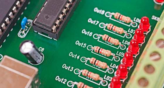
Circuit board names are: circuit board, PCB board, aluminum substrate, high frequency board, thick copper board, impedance board, PCB, ultra-thin circuit board, ultra-thin circuit board, printing (copper etching technology) circuit board, etc. The circuit board makes the circuit miniaturized and intuitive, which plays an important role in the mass production of fixed circuit and the optimization of electrical appliance layout.
Selection of welding wire for circuit board welding
1, according to the welding structure of the steel selection wire for carbon steel and low alloy high strength steel, mainly according to the principle of "equal strength matching", choose to meet the mechanical properties of the welding wire. For heat-resistant steel and weather-resistant steel, it mainly focuses on considering the consistent and similar chemical composition of weld metal and base metal, so as to meet the requirements of heat resistance and corrosion resistance.

2. According to the quality requirements of welded parts (especially impact toughness), the selection of welding wire is related to welding conditions, groove shape, protective gas mixing ratio and other process conditions. Under the premise of ensuring the performance of welded joints, the welding material to achieve the maximum welding efficiency and reduce the welding cost should be selected.
3, according to the field welding position corresponding to the plate thickness of the welded parts to choose the diameter of the welding wire, determine the current value used, refer to the product introduction of each factory and experience, select suitable for welding position and the use of current of the wire brand.
3. Judgment of channel relationship
3.1 Proposal of threshold voltage
If VA is taken as the measured voltage, theoretically when VA=0, it should be channel, VA> The value of VA varies with the resistance value between the two measurement channels. However, since the analog multiway switch itself has a nonignorable on-off resistance RON, in this way, after the formation of the measurement path, if it is a path, VA is not equal to 0, but equal to the voltage drop on RON. Since the purpose of measurement is only to know the on-off relationship, it is not necessary to measure the specific value of VA, so it is only necessary to use the voltage comparator to compare whether VA is greater than the voltage drop on RON. Set the threshold voltage of the voltage comparator equal to the voltage drop on the RON. The output of the voltage comparator is the measurement result, which is a digital quantity that can be read directly by the microcontroller.
3.2 Determination of threshold voltage value
It is found that RON has individual differences and is also related to the ambient temperature, so the threshold voltage loaded should be set one by one with the closed analog switching channel, which can be realized by programming the D/A converter.
The circuit shown in Figure 2 can be used to determine the threshold data conveniently, by closing the switch pair Ⅰ-1 and Ⅱ-1 in turn; Ⅰ-2, Ⅱ-2; ... ; Ⅰ-N, Ⅱ-N; After each pair of switches is closed, the number is sent to the D/A converter, and the number is increased from small to large. At this time, the output of the voltage comparator is measured. When the output of the voltage comparator changes from 1 to 0, the data at this time corresponds to VA. This measures the VA of each channel path, that is, the voltage drop across a pair of open and closed RON. For a high-precision analog multiway switch, the individual RON difference is small, so half of the VA automatically measured by the system can be approximated as the corresponding data of the voltage drop on the respective RON of this pair of switches, which is the threshold data of each analog switch at the current temperature.
Any adjacent power layer or other plane that provides a low reactance path to GND with appropriate capacitors at both ends of the signal can be used as the return plane of the signal. In common applications, the corresponding chip IO power supply for sending and receiving is often consistent, and there are generally 0.01-0.1uF decoupling capacitors between the respective power supply and the ground, which are precisely at both ends of the signal, so the reflux effect of the power plane is second only to the ground plane. And use other power plane to do reflux, often not at both ends of the signal to the ground low reactance path. In this way, the current induced in the adjacent plane will look for the nearest capacitor to return to earth. If the "nearest capacitor" is far away from the beginning or end, the backflow will have to travel a long way to form a complete backflow path, which is also the backflow path of adjacent signals. This same backflow path has the same effect as common ground interference, which is equivalent to crosstalk between signals.
For some unavoidable cross-source segmentation, a high-pass filter composed of capacitors or RC series can be connected at the place of cross-segmentation (such as a 10-ohm resistance series 680p capacitor, the specific value depends on its signal type, that is, to provide a high-frequency backflow path, but also to isolate the low-frequency crosstalk between the planes). This may involve adding capacitors between the power planes, which seems a bit funny, but it certainly works. If some specifications do not allow it, the capacitor can be directed to ground on both planes at the split.
For the use of other planes to do reflux, it is best to increase several small capacitors to the ground at both ends of the signal to provide a reflux path. But this is often difficult to achieve. Because most of the surface space near the terminal is occupied by matching resistors and chip decoupling capacitors.


