
Professional PCB manufacturing and assembly
Building 6, Zone 3, Yuekang Road,Bao'an District, Shenzhen, China
+86-13410863085Mon.-Sat.08:00-20:00


To get around the problems caused by lack of documentation and poor understanding of component function, test system manufacturers can rely on software tools that automatically generate test patterns according to random principles, or on non-vector methods, which are only a stopgap solution.
Complete pre-test documentation includes parts lists, PCB design data (mainly CAD data) and detailed information about the functions of the service components (such as data sheets). Only when you have all the information is it possible to write test vectors, define component failure styles, or make certain pre-adjustments.
Certain mechanical data is also important, such as those needed to check that components are soldered and positioned properly. Finally, for programmable components, such as flash memory, PLD, FPGA, etc., if not in the final installation of programming, is in the test system should be programmed, also must know the respective programming data. The programming data of the flash element should be intact. If the flash chip contains 16Mbit data, 16Mbit data should be used to prevent misunderstandings and address conflicts. For example, this can happen if you use a 4Mbit memory to provide only 300Kbit of data to a component. Of course, the data should be prepared in a popular standard format, such as Intel's Hex or Motorola's S recording structure. Most test systems, provided they can program flash or ISP components, can interpret these formats. Much of the information mentioned above is also necessary for component manufacturing. Of course, a clear distinction should be made between manufacturability and testability, as these are completely different concepts and thus constitute different premises.

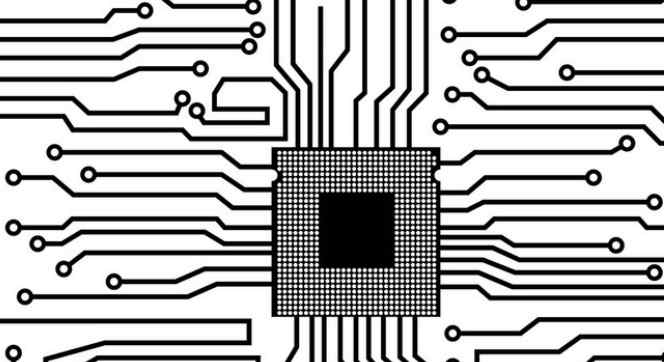
4, good testability of mechanical contact conditions
Even circuits with very good electrical testability may be difficult to test without considering the basic rules of mechanics. Many factors can limit electrical testability. If the test points are insufficient or too small, it is difficult for the probe bed adapter to reach every node of the circuit. If the position error and size error of the test point are too large, it will cause the problem of poor test repeatability. A series of recommendations regarding the size and positioning of the latching holes and test points should be heeded when using the probe bed dispenser.
5. Electrical preconditions for optimum testability
Electrical preconditions are as important to good testability as mechanical contact conditions, and one cannot be without the other. A gate circuit cannot be tested either because it cannot reach the start input through the test point or because the start input is in the encapsulation shell and cannot be contacted externally. In principle, both cases are bad and make the test impossible. In the design of circuits, it should be noted that all components to be tested by on-line testing should have some mechanism that enables the individual components to be electrically insulated. This mechanism can be achieved by disabling the input, which can control the output of the component in a static high ohm state.
Although almost all test systems can drive the state of a node to any state by Backdriving, it is better to have a forbidden input for the node involved. First, bring the node to a high ohm state, and then "gently" add the corresponding level.
Similarly, the beat generator is always disconnected directly from behind the oscillator via a starter lead, gate circuit, or plug bridge. The starting input must never be connected directly to the circuit, but through a 100 ohm resistor. Each component should have its own start, reset, or control pin. It is necessary to avoid having many components whose startup inputs share a single resistance connected to the circuit. This rule applies to ASIC components, which should also have a lead pin through which the output can be brought to a high ohm state. If the element can be reset when the operating voltage is turned on, it is also very helpful to trigger the reset by the tester. In this case, the component can simply be placed in the specified state before testing.
Unused component pins should also be accessible, as undetected short circuits in these areas can also cause component failures. In addition, unused gate circuits are often used for design improvements later, and they may be converted into circuits. So it is also important that they are tested from the start to ensure that their artifacts are reliable.
Three elements of EMC suppression in PCB
May 14,2023


Just upload Gerber files, BOM files and design files, and the KINGFORD team will provide a complete quotation within 24h.