
Professional PCB manufacturing and assembly
Building 6, Zone 3, Yuekang Road,Bao'an District, Shenzhen, China
+86-13410863085Mon.-Sat.08:00-20:00

With the large-scale commercial use of 10G and 25G+ products, the monitoring of PCB board insertion loss is an important indicator of control in the process of high-speed product development and mass production. Through the selection of different PCB materials and PCB processing technology, the vector network analyzer was used to comprehensively analyze the influence of high-speed board, copper foil type, glass fiber cloth type, solder resistance ink, roughing liquid and surface treatment technology on the characteristics of high-speed PCB insertion loss, which can provide a reference for the material selection and processing technology design of high-speed PCB.
First, test methods
1. Test materials and instruments
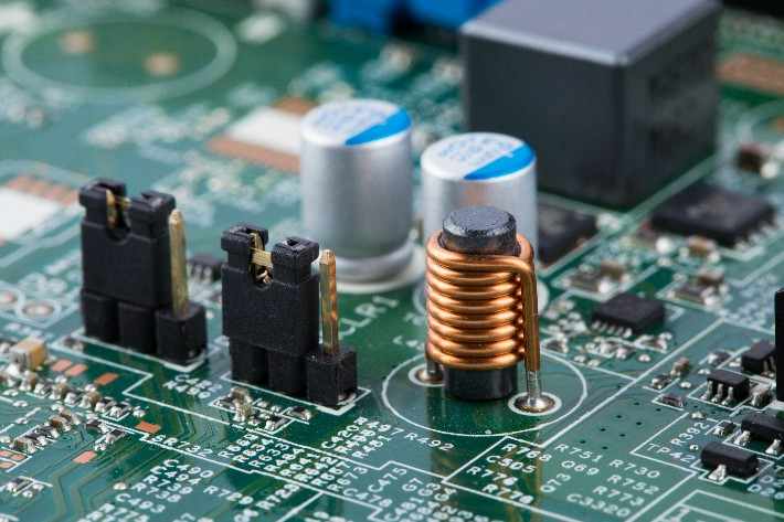
Materials: low loss copper coated plate and semi-cured sheet, HTE, RTF and HVLP copper foil, low loss solder resistance ink, low roughness potion, etc.
Test instrument: Impedance and loss were measured by vector network analyzer (rise time: 22.3ps, bandwidth: 20 GHz).
2. Experimental design
The test design was k, the Top layer, L3 layer and L5 layer were wire routing layers, and the impedance of single end and differential signal lines were designed to be 50 Ω and 100 Ω respectively. FD method was used to test insertion loss, and TRL (Thru Reflect-Line) method was used to correct.
The test plates were made of different materials or processing techniques, so as to evaluate the influence of materials or processing techniques on PCB insertion loss.
Process design: opening → inner graph → inner AOI→ brown → lamination → drilling → plasma → copper plating → plate plating → tin plating → back drilling → tin → outer dry film → graphic plating → outer etching → outer AOI→ Surface treatment → impedance test → molding → test → milling →FQC
Two, results and discussion
1. The influence of different grades of high-speed boards on the loss performance of high-speed PCB
High speed products require high transmission rate and low signal loss, and these properties are closely related to the dielectric constant and loss factor of PCB board. Generally, according to the level of Loss factor, the substrate material can be divided into (Df: 0.015~0.020), Mid,Loss (Df: 0.010~0.015), Low Loss (Df: 0.0065~0.01), Very Low Loss (Df: 0.003~0.0065) and Ultra Low Loss (Df: < 0.003). In order to analyze the influence of different grades of high-speed materials on PCB insertion loss, three materials commonly used in the industry were selected: For X7, X8 and X9, the FD method was used to test the insertion loss values at different frequencies under the same layup and impedance design. For the differential strip line, the material loss of X7, X8 and X9 at 8 GHz was 0.256 dB/cm, 0.182 dB/cm and 0.147 dB/cm, respectively. At 12.5GHz, the material loss of X7, X8 and X9 is 0.342 dB/cm, 0.256 dB/cm and 0.202 dB/cm, respectively. At different transmission frequencies, the insertion loss of X7 is 20%~28% larger than that of X8, and the insertion loss of X8 is 18%~22% larger than that of X9. Therefore, the selection of substrate material has great influence on PCB loss performance.
2. Influence of glass fiber type on loss performance of high-speed PCB
PCB substrate is composed of resin, glass fiber, copper foil, filler, etc., the dielectric constant and loss factor of the substrate is closely related to its composition. In order to meet the needs of PCB high-speed signal transmission, it is necessary to reduce the dielectric constant and loss factor of the substrate. Therefore, in recent years, low loss resin materials have been constantly introduced. In addition, glass fiber manufacturers are also committed to developing glass fiber cloth with low dielectric constant and low loss factor. For example, the high speed substrate has been widely used in the NE-glass is PCB's low dielectric constant, low loss factor glass fiber cloth. Compared with E-glass, the dielectric constant and dielectric loss of NE-glass are significantly reduced, with a dielectric constant of 4.4 (1 MHz) and a loss factor of 0.0006 (1 MHz).
3. Influence of different copper foil types on loss performance of high-speed PCB
With the development of high-speed and high-frequency signal transmission, skin effect has more and more influence on signal transmission quality and signal integrity, and the transmission thickness of signals in conductors is getting thinner and thinner. In order to reduce signal transmission loss, high-speed PCB board is usually equipped with copper foil with low roughness. According to the different roughness, PCB commonly used copper foil has low profile copper foil (HVLP copper foil), reverse copper foil (RTF copper foil) and high elongation copper foil (HTE copper foil).
4. Influence of copper foil coarsening treatment on loss performance of high-speed PCB
When PCB circuits are made, the copper surface is usually roughened to increase the adhesion between the dry film (or wet film) and the copper surface. At the same time, in order to increase the binding force between PP and copper foil and improve the reliability of PCB, the copper surface will also be roughened before pressing. Among them, the coarsening process often used in line production includes grinding plate or chemical micro-etching, etc. Coarsening before pressing is generally brownish. With the development of high-speed signal, the copper foils used for substrate are generally low-roughness copper foils (VLP, HVLP, etc.), but the traditional coarsening process will increase the roughness of copper foils and lead to the increase of conductor loss. In order to improve the influence of coarsening treatment on loss performance in PCB process, potion manufacturer developed a low roughness coarsening solution specially for improving PCB loss performance to reduce the roughness of copper foil coarsening treatment.
5. The influence of different solder resistance ink on high speed PCB loss performance
The loss factor of solder resistance ink used in high-speed PCB is much larger than that of board. Therefore, for the outer circuit of high-speed PCB, the factors affecting the signal transmission loss in addition to the PCB design and material selection (board, copper foil type, glass fiber type, etc.), the selection of solder resistance ink also has a great impact on the loss performance of the outer layer line. In order to improve the signal transmission performance of high speed PCB outer circuit, low loss solder resistance ink has been developed in recent years. In order to analyze the difference of the influence of conventional ink and low loss ink on the outer layer transmission line loss, the low loss plate was used to make differential microstrip line, and then the two kinds of ink were screened respectively and the change of line loss performance before and after screen printing was tested.
6. Influence of surface process on high speed PCB loss
As we all know, bare copper itself has good solderability. However, after exposure to air, the copper conductor on PCB surface will oxidize rapidly, thus leading to the deterioration of PCB performance. Therefore, surface treatment of copper surface is required to ensure good solderability and reliability. However, after PCB surface treatment, the microstrip line loss of solder resistance window will change, affecting the signal transmission performance. The selection of different surface treatment processes will have different effects on PCB conductor loss. For high-speed PCB, the selection of surface treatment processes should consider not only the solderability, but also the impact on signal loss.
In addition to the influence of the above processing technology on the loss, back drilling design and stump control also have a certain influence on PCB loss. By reducing the length of the stump through the hole through the back drilling, the interference of signal reflection on the loss test can be significantly reduced and the loss performance of the inner line can be improved.


Just upload Gerber files, BOM files and design files, and the KINGFORD team will provide a complete quotation within 24h.