
Professional PCB manufacturing and assembly
Building 6, Zone 3, Yuekang Road,Bao'an District, Shenzhen, China
+86-13410863085Mon.-Sat.08:00-20:00


Online or reprogramming course of Smt mounter
On line programming of SMT machine refers to the use of teaching attached to some machines for program editing, and the use of SMT program editing function in the application software of SMT machine Online programming methods include teaching programming and manual input programming In addition, the component placement coordinates on the circuit board and component database can also be set and calibrated on the machine
Teaching program design of chip mounter
The traditional Smt placement machine programming method uses the manual teaching method of the placement machine, using the teaching box, that is, moving the camera to find the coordinate positions of all the placement components on the circuit board, and then finding other information about the components, such as the location information of the components, such as digital, program code and placement angle, to manually input the Smt placement machine. Instructional programming is the simplest basic programming method, usually used for old medium speed machines. This method takes up the production time of the machine, while the manual teaching method is time-consuming, laborious and error prone to find a point for a circuit board with hundreds of SMD components.
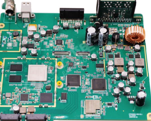
Circuit board

1. Reclaiming and teaching: select the nozzle type, use the teaching box to move the placement head to the top of the feeder, put down and pick up the parts, and determine the centering method. The control computer of the Smt placer will automatically record the XYzQ coordinates of the reclaiming and other reclaiming correction methods.
2. SMD teaching: after data teaching, pick up the element, correct and rotate the angle, use the teaching box to move the placement head to the top of the element welding pattern on the circuit board, and use the circuit board identification monitor to determine the center of the element. Then place the component on the circuit board and press Enter.
3. Complete circuit board transmission, feeder and nozzle setting and position teaching: after recovery teaching and placement teaching, placement sequence programming and teaching can be carried out. The placement sequence can be programmed through the teaching box, or the automatic programming function attached to the mounter software can be used for automatic optimization.
2. Program Design for Manual Input of Chip Mounter
All mounters can be programmed by manual input. In the placement list of the programming software, enter the RefID of the component, select the component database code of the component, and enter the x, y coordinates and rotation angle of the component. This is the most important point of the SMT program. Then input the station number of various component codes and optimize the placement order to complete the placement machine programming.
3. Position coordinate teaching correction
Because sometimes SMT components cannot obtain the position, it will be very troublesome to change the coordinates after placing the first circuit board Therefore, some SMT machines also provide the calibration function of component coordinates, which is also called enhancement program Settings (Enhanced Product Setup). The enhanced program setting can effectively improve the accuracy of program design by using the PEC camera of the machine to visually display the graphics of placement positions
What if we need to edit the Smt mounter again?
Step 1: First of all, re program the system: The mounter system usually uses two programming methods: manual programming and computer programming. Many low-level mounters usually use manual teaching programming, while fully active mounters (such as Huawei Guochuang mounters) can fully use computer automation for programming.
Step 2: Replace the original production feeder: In order to reduce the time for the placement machine to replace the feeder, the more common method is to use the "quick release" feeder, and the faster method is to replace the feeder structure, so that the feeder of each component on the substrate type of the placement machine is installed on a separate feeder frame for replacement.
Step 3: Adjustment of transmission organization and positioning table: When the size of the replaced substrate is different from that of the current equipment, the width of the substrate positioning table and the transmission organization of the substrate should be adjusted. The full active mounter can be adjusted actively under the program control, and the next level mounter can be adjusted manually.
Step 4: Replace the placement head: When the SMT substrate to be installed exceeds the size of the placement head, the placement head of the placement machine is often replaced or adjusted when the substrate type changes Most full active placement machines can actively replace and adjust the patch heads under program control, while some small brand implant machines need to manually perform such operations
The above is the explanation given by the editor of pcb circuit board company.
If you want to know more about PCBA, you can go to our company's home page to learn about it.
In addition, our company also sells various circuit boards,
High frequency circuit board and SMT chip are waiting for your presence again.


Just upload Gerber files, BOM files and design files, and the KINGFORD team will provide a complete quotation within 24h.