
Professional PCB manufacturing and assembly
Building 6, Zone 3, Yuekang Road,Bao'an District, Shenzhen, China
+86-13410863085Mon.-Sat.08:00-20:00

PCBA through-hole and Smd reflow and infrared soldering
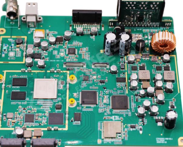
SMT patch and PCBA through-hole
SMT chip and PCBA through-hole: Advantages and disadvantages When the printed circuit board becomes an essential component in the production of electronic products for the first time, the through-hole component is the only component that can be used. However, with the passage of time, surface mount technology (SMT) parts gradually become more and more popular, until they finally become the main component packaging form used on today's PCB. Nowadays, SMT parts are popular for many reasons:
Size: The conductor does not need to be drilled By default, this SMT part is a smaller part This is more attractive to designers who are trying to assemble more circuits on smaller circuit boards in today's electronic products
Cost: Since SMT parts are smaller by default, the manufacturing cost is also lower. This makes SMT parts more cost-effective than through-hole parts.
Usability: As SMT components become smaller and cheaper, they have replaced through-hole components. Especially for passive devices such as resistors and capacitors, SMT component packaging is no longer the only option.
Circuit board

Power efficiency: smaller components shorten the transmission distance of electrical signals, thus shortening the flight time of signals. This makes surface mount components superior to through hole components in terms of power efficiency.
For these reasons, it is easy to believe that all PCB assemblies should be surface mount components. However, there are many good reasons for using through-hole parts when assembling circuit boards:
Power supply: SMT packaging is not a good choice for components used in high-power circuits. High power components usually contain more metal, which makes surface mount welding technology more difficult to achieve good welding results. In addition, larger power components usually require stronger mechanical connections through vias to achieve high voltage, thermal stability, and mechanical stability.
Strength: the strength provided by components such as connectors, switches or other interface components that need to be welded to the drill hole. Constant physical stress of components in normal use may eventually destroy SMT solder joints.
Availability: Some components, especially the larger components used in high-power applications, have not been provided with real SMT equivalent components.
Smd reflow welding process and advantages of infrared welding
1. SMD reflow:
Infrared heating reflow soldering, commonly known as infrared soldering, is mainly used to weld substrates with surface mount components. Generally, the substrate is conveyed by a machine with a series of heating elements, such as a rod radiator positioned transversely in the conveying direction. The components can be placed above the substrate being transported, but in many cases there are also components under the substrate to increase the heating rate and improve temperature uniformity. The possible settings for this type of machine are shown in the following figure.
SMD reflow
Schematic diagram of infrared welding furnace. The main characteristic of heating is the wavelength of the parts in the machine.
2. Advantages of IR welding:
i) This is a clean and environment-friendly method
Ii) The heating is non-contact and does not require precise positioning of the product to be welded
Iii) Easy control of heating power
The main disadvantage of infrared heating is that the heating rate is different, which is caused by the different absorption coefficients of the data used and the thermal quality of different components, which is related to the surface area that can be exposed to infrared radiation.
The temperature in the infrared furnace is a mixture of radiation and convection, which is not clear at present. It is almost meaningless to measure the temperature with a thermocouple suspended in the furnace; The only useful method is to measure the temperature of a specific product as it is transported through the furnace. If there are heaters under and above the conveyor belt (usually), they can influence the temperature control of each other, especially when they can "see" each other.
The main difficulty of infrared welding of circuit boards with surface mount components is that SMT modules require different heating rates for different heat This means that when welding multiple components at the same time, some may exceed the welding temperature, while others are far away from this temperature Some components will reach intolerable high temperatures when heating continues until reflow In the actual furnace, the three-step heating method is usually used: start rapid heating, balance, and fast heating again For the second step, the area in the furnace can be adjusted to create a temperature platform in the area between 120 ° C and 1600 ° C, where the temperature rises to about 0. 50 kilos/When the welding temperature recovers to a sharp rise, the temperature difference can be homogenized The welding phase requires rapid heating to limit the duration of the phase In addition, the most important thing is that there is no or only a small temperature difference between different parts before the welding phase starts to heat rapidly, in order to avoid any such welding defects, such as cold welding and leaching Ideally, at the end of the homogenization step, that is, before reflux, the temperature of the light component and the heavy component is actually the same However, this is difficult to achieve in production recycling systems, even if these systems are long The temperature time curve was measured in a large production furnace; In the first step, the pin temperature of SOT-23 package rises faster than that of PLCC-68 package; Then the temperature difference decreases In the second stage of heating, the difference is slightly increased and then decreased again After that, the SMT welding step with rapidly increased temperature difference started, but at this time, the difference between the two temperature curves is still very large, and the difference between the peak temperatures reached here is also very large
Chip thrust test and through-hole technology
Dec 01,2022


Just upload Gerber files, BOM files and design files, and the KINGFORD team will provide a complete quotation within 24h.