
Professional PCB manufacturing and assembly
Building 6, Zone 3, Yuekang Road,Bao'an District, Shenzhen, China
+86-13410863085Mon.-Sat.08:00-20:00

SMT wafer reflow soldering process guide
In order to improve the pass through rate of PCB products, in addition to reducing visible solder joint defects, it is also necessary to overcome intangible defects, such as virtual welding, poor bonding strength of solder interface, and high internal stress of solder joints Therefore, the reflow welding process must be carried out under controlled conditions Reflow soldering process requirements are as follows:
(1) According to the temperature curve of the solder paste used and the specific situation of PCB, combined with the welding theory, set the ideal reflow welding temperature curve, and regularly test the real-time temperature curve to ensure the quality and process stability of reflow welding.
(2) The welding should be carried out in accordance with the welding direction of the PCB design
(3) During welding, the vibration of conveyor belt shall be strictly prevented.
(4) After welding, the welding effect of the first printed board must be checked. Check whether the welding is sufficient, whether there are traces of insufficient solder paste melting, whether the surface of solder joints is smooth, whether the shape of solder joints is semi meniscus, the status of solder balls and residues, bridging and virtual welding, and also check the change of PCB surface color. After reflow, allow the PCB to have a little but uniform discoloration, and adjust the temperature curve according to the test results. During the whole batch production process, the welding quality shall be checked regularly.
Reflow soldering is to design a temperature distribution (temperature distribution), allowing the product to increase and decrease the temperature along the design curve to achieve the purpose of welding and curing. The temperature distribution is a function of the temperature and time applied to the circuit board. When drawn using the Cartesian plane, any given time in the reflow process represents a curve formed by the temperature of a specific point on the PCB. In the assembly of printed circuit boards using surface mount components, in order to obtain high-quality solder joints, optimizing the reflow temperature curve is one of the most important factors.
1) Basis for setting reflux temperature curve
(1) Set according to the temperature distribution of solder paste. Solder pastes with different metal contents have different temperature curves, which should be set according to the temperature curves provided by the solder paste supplier (mainly controlling the heating rate, peak temperature and reflux time).
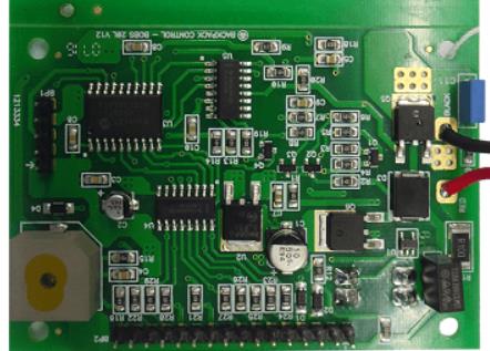
Circuit board

(2) Set according to PCB data, thickness, multilayer board, size, etc
(3) It is set according to the assembly density of components, the size of components and whether there are special components (such as BGA). CSP。
(4) Set according to the specific conditions of the equipment, such as the length of the heating zone, heat source information, the structure of the reflux furnace and the heat conduction method.
(5) Determine the set temperature of each temperature zone according to the actual position of the temperature sensor in the heating zone. If the temperature sensor is located in the heating element, the set temperature is about twice the actual temperature; If the sensor is located at the top or bottom of the furnace chamber, the set temperature may be about 30 higher than the actual temperature.
(6) Set according to the exhaust air volume. Generally, the reflux furnace has specific requirements for the exhaust volume, but the actual exhaust volume will sometimes change due to various reasons. When determining the temperature curve of the product, the exhaust volume shall be considered and measured regularly.
(7) The ambient temperature also affects the furnace temperature. Especially for the reflux furnace with short heating temperature zone and narrow furnace body width, the furnace temperature is greatly affected by the ambient temperature, and convection air at the inlet and outlet of the reflux furnace should be avoided.
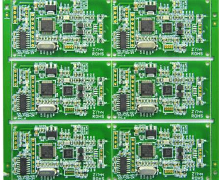
Smart motherboard chip processing
The most important parameters that affect the shape of the temperature curve are the speed of the conveyor belt and the temperature setting of each area. The conveyor speed determines the duration of substrate exposure to the set temperature of each zone. The added duration allows the temperature on the circuit to approach the temperature setting for that area. The total duration of each area determines the total welding time; The temperature setting of each area will affect the temperature rise rate of the PCB. Increasing the setting temperature of the area can make the substrate reach the given temperature faster.
(1) Test tools: temperature curve tester, thermocouple.
Many reflux furnaces now have thermometers. Thermometers are usually divided into two categories: real-time thermometers, which transmit temperature time data and draw charts in real time; Another kind of thermometer collects and stores data, and then uploads it to the computer.
Thermocouples must be long enough to withstand typical furnace temperatures.
The information contained in the solder paste characteristic parameter table is crucial to the temperature distribution, such as the duration of the temperature distribution, the active temperature of the solder paste, the melting point of the alloy and the maximum reflux temperature.
(2) Location and fixation of thermocouples:
1. Connect the thermocouple of the temperature curve tester to 3 to 6 test points selected on the SMA board. The selection of test point is determined by the point with the largest heat absorption and the point with the smallest heat absorption, and its temperature represents the welding temperature on the SMA plate.
2. A better way to fix thermocouples is to use high-temperature solder, such as silver tin alloy, with the solder joints as small as possible. In addition, you can cover the thermocouple with a small amount of hot compound (also known as hot grease or hot grease) spots and then stick them with high temperature tape. Another method is to use high-temperature glue to connect thermocouples, such as cyanoacrylate adhesive. This method is usually less reliable than other methods.
(3) Steps to determine the reflux temperature curve: Before the test, it is necessary to have a basic understanding of the ideal temperature curve. Theoretically, the ideal curve consists of four parts or intervals, with the first three regions heated and the last region cooled. The more temperature regions of reflux furnace are, the more accurate and close the profile of temperature curve will be.
1. Set the speed of the conveyor belt: This setting will determine the time the PCB spends in the heating channel. Typical solder paste parameters require a heating curve of 3 to 4 minutes. The exact conveyor speed is obtained by dividing the total heating channel length by the total heating temperature sensing time.
2. Set the temperature of each temperature zone: the displayed temperature only represents the temperature of the thermocouple in this zone. If the thermocouple is close to the heat source, the displayed temperature will be higher than the temperature of the area; The closer the thermocouple is to the direct channel of the PCB, the greater the response of the displayed temperature to the interval temperature. Before setting the temperature of each temperature zone, consult the manufacturer to understand the relationship between the displayed temperature and the actual temperature.
3. When the machine starts and the furnace is stable (all actual displayed temperatures are equal to the set temperature), the curve starts: put the connected thermocouple and PCB of the temperature curve tester into the conveyor belt, and trigger the thermometer to start recording data. For convenience, some thermometers (including the trigger function) will automatically start the thermometer at a relatively low temperature, which is slightly higher than the human body temperature of 37 ° C (98.6 F.). For example, an automatic trigger of 38 dragons (100 degrees Fahrenheit) allows the thermometer to work almost as soon as the PCB is placed in the conveyor belt and furnace, so that the thermocouple will not be triggered incorrectly when in hand.
4. After generating the initial temperature curve, compare it with the curve inferred by the solder paste supplier: first, it must be verified that the total time from the ambient temperature to the reflux peak temperature is consistent with the required heating curve time. If it is too long, increase the belt speed proportionally; If it is too short, the opposite is true.
5. Compare the measured temperature curve shape with the required shape and adjust it. When adjusting, the deviation from left to right (process sequence) shall be considered. For example, if there is a difference between the preheating zone and the re looping zone, first correct the difference between the preheating zone. In general, it is best to adjust one parameter at a time and run this curve setting before making further adjustments. This is because changes in a given partition also affect the results of subsequent partitions.
6. When the final figure matches the required figure as much as possible, record or store the furnace parameters for future use.
The above is the explanation given by the editor of pcb circuit board company.
If you want to know more about PCBA, you can go to our company's home page to learn about it.
In addition, our company also sells various circuit boards,
High frequency circuit board and SMT chip are waiting for your presence again.


Just upload Gerber files, BOM files and design files, and the KINGFORD team will provide a complete quotation within 24h.