
Professional PCB manufacturing and assembly
Building 6, Zone 3, Yuekang Road,Bao'an District, Shenzhen, China
+86-13410863085Mon.-Sat.08:00-20:00

Causes of PCB failure:
According to relevant data reports, up to 78% of hardware failures are caused by poor welding processing.
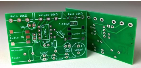
pcb
In case of hardware failure, he is willing to spend a lot of time and energy in sample debugging and analysis, which delays the project progress. If they can't find the bad reason, they will also habitually think that the problem is in the design of software and hardware circuits. When doing hardware debugging, engineers often consider many profound potential incentives, but they are unwilling to doubt the most obvious mistakes:
Case 1: A large number of decoupling capacitors are densely distributed near the CPU power supply. Due to the redundant solder PCB welding processing during the welding process, an electric PCB capacitor is short circuited. As a result, the hardware engineer goes to check the cause of the short circuit one by one, spending a lot of time.
Case 2: Due to the faulty soldering of a signal in the high-speed signal part of the DDR, the system seems to work normally when transmitting ordinary small amounts of data. However, when doing burst operations with large amounts of data, such as loading the operating system and playing high-definition movies, errors will often be reported. However, it is often mistaken for software reasons, and PCB software engineers have no results when looking at the code.
Case 3: High speed signal interface connector. Due to faulty soldering of a signal, PCB soldering causes the system to work at a lower
Case 5: Due to the poor welding of the inductance part, the PWM dimming function of the LED fails, and PCB welding processing
Engineers spend a lot of time confirming whether it is a software or hardware problem.
Case 4: Due to improper control of time and temperature during welding, plastic structures inside connectors such as LCD and USB were melted and deformed due to high temperature, resulting in an unexpected disconnection of a signal, resulting in no display on LCD and no communication on USB, which was mistaken for a software drive problem.
These problems seem simple, but they are also made up of a lot of welding details and steps, and these links are linked to each other. Errors in any link will lead to problems. Therefore, during hardware debugging, engineers are recommended to observe the welding quality of your prototype first,
1. Is the material correct?
2. Is the foot position correct?
3. Whether there is empty soldering, faulty soldering and tin connection
4. Is the solder paste full and reflective after passing through the furnace?
5. Does the structural part of the connector melt at high temperature?
6. Does the chip position correspond to the silk screen?
After checking the above "shallow" items, PCB welding processing, and then focus on those "deep" problems! This is the smart choice.


Just upload Gerber files, BOM files and design files, and the KINGFORD team will provide a complete quotation within 24h.