
Professional PCB manufacturing and assembly
Building 6, Zone 3, Yuekang Road,Bao'an District, Shenzhen, China
+86-13410863085Mon.-Sat.08:00-20:00

Uncover a SMT repair challenge that we have to face
With the rapid development of electronic manufacturing technology, more and more customers' demands for PCB repair are also increasing. New solutions and technologies are needed to solve those new demands.
Most customers need to repair SMT PCB effectively. In the years to come, more people will pay attention to and generally discuss the following topics:
Smaller devices: miniaturization
Processing of large size PCB: dynamic preheating applied to large board repair
Repeatability of repair process: application of flux and solder paste (dip coating technology), removal of residual tin (automatic tin cleaning), supply of raw materials, treatment of multiple devices, and traceability of repair
Operation support: higher degree of automation, software guided operation (friendly human-computer interaction interface)
Cost effectiveness: repair system meeting different budgets, ROI evaluation
In a precise flow production line, many parameters need to be observed and controlled, including:
When desoldering and extracting components, other components adjacent to it shall not be affected
Add a new paste to the small spot
Device absorption, calibration and mounting
PCB coating
PCB cleaning and others
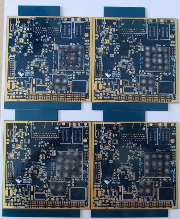
However, due to the existence of 01005 devices, the challenge of rework has inevitably emerged. On the one hand, the device size is getting smaller and smaller, and the assembly density is getting higher and higher. On the other hand, the size of PCB is getting larger and larger. Benefiting from the development of communication products and network data transmission technologies (cloud computing, Internet of Things), the computing power of computer centers has been growing rapidly. At the same time, the motherboard size of computing systems has been growing. This poses a challenge. How to evenly and completely preheat a 24 "x48" (610 x 1220mm) multilayer PCB during the repair process?
In addition, in the growing field of electronic manufacturing, the repair process has been recognized as a part of electronic assembly, and the recording and tracking of the repair of a single circuit board has become an essential requirement. In the above mentioned topics, the blueprint of the future repair capability is mainly described. Next, two topics will be introduced. Other topics are also very important in the future repair. Many of them have passed the practice certification and are feasible, so they just need to be added or improved in the existing repair equipment.
Removal of residual solder - tin removal
Different from the production process, it is a very important step to remove the residual solder on the pad when repairing the electronic circuit board. This step is essential for reinstalling a new component to the specified location and obtaining a solder joint with good repeatability and high reliability. Nowadays, the common manual operation mode depends on the skills of operators, and there are hidden risks.
The modules that manually operate but non-contact to remove residual tin have the following advantages:
High repeatability and non-contact solder extraction
No risk of pad breakage and peeling
No risk of damage to insulating paint
Prevent contamination of flux or solder on PCB
The method is to use soft hot air to preheat the bottom of the PCB until the solder remaining on the PCB melts, and then use a vacuum nozzle to quickly remove the liquid solder from the PCB surface.
In addition to the known technology of melting solder by hot air and removing residual tin by vacuum, it is also very important to control the height of suction nozzle to ensure that the circuit board is not damaged. In the first operation, the height of the suction nozzle often needs to be adjusted manually. In the advanced system, the equipment can automatically adjust the height through pressure sensing or triangulation laser measurement.
For high-quality daily operation, solder separation, flux filtration and convenient maintenance are very important.
This module does not exist independently of the repair equipment and needs to be integrated in the equipment. During the tin removal process, the temperature of the circuit board needs to be sensed, and the PCB bottom preheating function must be active and controllable.
The market clearly requires that the repair equipment has flexible adaptability, simple operation, and higher automation. The equipment does not depend on operators. Based on the above requirements, a set of interactive interfaces with clear structure for operators or equipment managers is necessary.
A clear expectation of the customer for the repair process is to achieve independent operators and obtain high-quality repair results. This is why more and more automated process flows are applied to repair equipment, and the improvement of HCI (Human Interaction Interface) is also proposed. In the repair process, the system with operation guidance and assistance can significantly reduce the mistakes of operators. The software interface with clear architecture can provide all necessary information required for each decomposition step, from temperature curve selection, component removal to final mounting and welding, and whether to add solder paste or solder paste.
All process steps are assisted, and operators are guided in the whole process and guided to the next process operation. When the system does not automatically execute, the pictogram will tell the user what to do next.
Computer aided mounting (CAP) is another means to obtain the best results through image processing and to assist operators. In this example, the screen called "comparator mode" shows the pads and component pins with color, as well as the virtual color after overlapping. The pin of the component is displayed in red, and the pad on the PCB is displayed in green. Once the images of the pin and pad overlap, they will be displayed in blue, indicating that the best patch conditions have been reached.
Unlike real-time camera images, the computer aided mounting function provides the best color contrast image through image processing. Just like the aviation control chart, the system clearly displays meaningful data to users. Therefore, the operator can focus on the task of position correction, and the fatigue of personnel will be minimized.
Another key element of computer aided mounting is the realization of digital image splitting mirror. It can provide multiple images (such as large QFP components) at high magnification to achieve the most accurate positioning. It replaces the optical magnification technology that requires a separate lens. The high-resolution camera image is divided into four areas, each of which shows a corner of the element. The positioning work is carried out in a high magnification image, and the process of matching pins and pads will become easier.
Overview and future prospects
In the electronic industry, even if the quality of products is constantly improving, repair will still be a challenging subject in the next decades. The integration of electronic assembly is getting higher and higher, and the products are getting more and more complex. The task of the supplier of the repair system is to follow the pace of the market and provide a solution that can successfully repair the circuit board. At the same time, the degree of automation in the part of repair equipment will continue to improve, and the auxiliary function of operation will become more important. In addition to technical challenges, high-end repair systems that integrate as many functions as possible need to find their way to derive entry-level products that meet market demands. Business and environmental protection will also benefit from less scrap and electronic waste.
Circuit board manufacturers, circuit board designers and PCBA manufacturers explain to you the challenge of SMT repair that you have to face.


Just upload Gerber files, BOM files and design files, and the KINGFORD team will provide a complete quotation within 24h.