
Professional PCB manufacturing and assembly
Building 6, Zone 3, Yuekang Road,Bao'an District, Shenzhen, China
+86-13410863085Mon.-Sat.08:00-20:00

1、 Explanation of wave soldering process
First, apply a small amount of patch adhesive (edge adhesive) to the bottom of the components or the busy edge of the PCB, and then place the chip components on the specified position on the printed surface for adhesive curing. The chip components are firmly bonded to the welding surface of the printed circuit board, and then the discrete components are inserted. Then the chip components and the plug-in components are wave soldering at the same time. Wave soldering process: insert the component into the corresponding component hole → precoat flux → pre bake (temperature: 90-1000C, length: 1-1.2m) → wave soldering (220-2400C) → cut off excess plug-in pins → check.
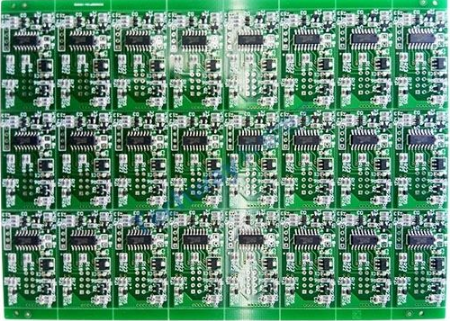
Wave soldering process flow
Wave soldering
Explanation of wave soldering process
1. Installation of wave soldering fixture
Fixture installation refers to the installation of clamping fixture for PCB to be welded, which can limit the degree of thermal deformation of the substrate, prevent the occurrence of tin emission, and ensure the stability of tin dipping effect.
2. Wave soldering flux system
The flux system is the first link to ensure the welding quality. Its main function is to evenly coat the flux, remove the oxide layer on the surface of PCB and components and prevent re oxidation during welding. The application of flux must be uniform and try not to produce accumulation, otherwise it will lead to welding short circuit or open circuit. There are many kinds of wave soldering flux systems, including spray type, spray flow type and foam type. At present, spray type flux system is generally used, and cleaning free flux is used, because the solid content of cleaning free flux is small, and the nonvolatile content is only 1/5~1/20. Therefore, a spray type flux system must be used to coat the flux, and an anti oxidation system must be added to the welding system to ensure that a thin, uniform layer of flux coating is obtained on the PCB, so that the solder bridging and pulling will not be caused by insufficient flux due to the scrubbing effect of the first wave and the volatilization of the flux. There are two ways of spray type: ultrasonic wave is used to strike the flux to make its particles smaller, and then it is sprayed on the PCB. The other is to use micro nozzle to spray flux under constant air pressure. This kind of spraying is uniform, small in particle size, easy to control, and the height/width of spray can be automatically adjusted, which is the mainstream of future development.
3. Wave soldering preheating system
A. Function of wave soldering preheating system
The solvent components in the flux will be heated and volatilized when passing through the preheater. Thus, the phenomenon of explosion caused by high temperature gasification of solvent components when passing through the liquid surface can be avoided, and the potential quality hazard of tin particles can be finally prevented. The slow temperature rise of the parts carried by the products to be dipped in tin when passing through the preheater can avoid the damage of the parts due to the physical effects caused by sudden heat during wave passing. When the preheated parts or terminals pass through the wave, the welding temperature of the solder joints will not be greatly reduced due to the factors of low temperature, so as to ensure that the welding can meet the temperature requirements within the specified time.
B. Wave soldering preheating method
There are three common preheating methods in wave soldering machine: ① air convection heating; ② Infrared heater heating; ③ Heating by combining hot air and radiation.
C. Wave soldering preheating temperature
Generally, the preheating temperature is 130~150 ℃, and the preheating time is 1~3min. The well controlled preheating temperature can prevent false soldering, pulling and bridging, reduce the thermal shock of solder wave on the substrate, and effectively solve the problems of PCB warping, delamination and deformation during welding.
4. Wave soldering system
The wave soldering system generally adopts double waves. During wave soldering, PCB first contacts the first wave and then the second wave. The first wave is the "turbulence" wave from the narrow nozzle, which has a fast flow rate and a high vertical pressure on the components, so that the solder has a good permeability to the welding ends of surface mounted components with small size and high mounting density; The component surface is scrubbed in all directions by turbulent molten solder, which improves the wettability of solder and overcomes the problems caused by the complex shape and orientation of components; At the same time, it also overcomes the "shielding effect" of the solder. The upward jet force of the turbulent wave is enough to discharge the flux gas. Therefore, even if there is no vent hole on the PCB, there is no effect of flux gas, which greatly reduces welding defects such as solder skips, bridging and incomplete welds, and improves welding reliability. After the first wave of products, due to the short time of tin dipping and the heat dissipation of parts, there are many defects such as short circuit, excessive tin, abnormal solder joint finish and insufficient welding strength after tin dipping. Therefore, the correction of poor tin dipping must be carried out immediately. This action is carried out by the second jet with flat and wide jet surface and stable wave. This is a "smooth" wave with a slow flow speed, which is conducive to the formation of a full weld. At the same time, it can effectively remove the excessive solder on the welding end, and make the solder on all welding surfaces well wetted. It corrects the welding surface, eliminates the possible pulling and bridging, and obtains a full defective weld, which ultimately ensures the reliability of component welding. Dual wave fundamentals.
5. Wave soldering cooling
Proper cooling of the circuit board after wave soldering and tin dipping is helpful to enhance the function of solder joint strength. At the same time, the cooled products are more conducive to the operation of operators behind the furnace. Therefore, the products after tin dipping need to be cooled
Reflow soldering
2、 Process explanation
Reflow soldering is to first apply a small amount of tin lead (SN/PB) solder paste to the bonding pad of the printed circuit board, then place the chip components on the specified position on the surface of the printed circuit board, and then place the printed circuit board with the components attached on the conveyor belt of the reflow soldering equipment, and complete the whole welding process of drying, preheating, melting and cooling from the furnace inlet to the outlet (about 5-6 minutes).
The reflow soldering process is surface mount plate, and its process is relatively complex, which can be divided into two types: single-sided mount and double-sided mount.
A. Single side mounting: pre coating solder paste → mounting (divided into manual mounting and machine automatic mounting) → reflow soldering → inspection and electrical testing.
B. Double side mounting: A-side pre coating solder paste → patch (divided into manual mounting and automatic machine mounting) → reflow soldering → B-side pre coating solder paste → patch (divided into manual mounting and automatic machine mounting) → reflow soldering → inspection and electrical testing.
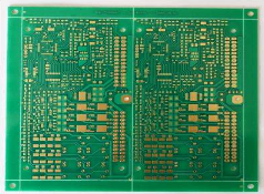
Reflow welding process flow
Detailed reflow welding process flow
1. Smt steel mesh template: the template is processed according to the designed PCB. General templates are divided into chemically etched (also known as etched) copper templates or stainless steel templates (low price, applicable to small batches, tests, and chip pin spacing>0.65mm); Laser cutting stainless steel template (high precision, high price, applicable to large batch, automatic production line and 0.3mm ≤ chip pin spacing ≤ 0.5mm).
2. SMT solder paste printing: Its function is to use a scraper to leak solder paste onto the PCB pad, so as to prepare for the mounting of components. The equipment used is screen printing machine (automatic and semi-automatic screen printing machine) or manual screen printing table, scraper (stainless steel or rubber), which is located at the front end of SMT production line.
3. SMT mounting: it is used to accurately install surface mounted components on the fixed position of PCB. The equipment used is a mounting machine (automatic, semi-automatic or manual), a vacuum suction pen or special tweezers, which is located behind the screen printing machine in the SMT production line.
4. Reflow soldering: it is used to melt the solder paste, so that the surface mounted components and PCB can be firmly soldered to achieve the electrical performance required by the design and precisely controlled according to the international standard curve. The equipment used is a reflow welder (full-automatic infrared/hot air reflow welder), which is located behind the SMT mounter in the SMT production line.
5. SMT circuit board cleaning: it is used to remove the substances that affect the electrical performance or the welding residues harmful to human body, such as flux, on the pasted PCB. If no cleaning solder is used, cleaning is not necessary. The equipment used for cleaning is an ultrasonic cleaner and a special cleaning solution. The location can be unfixed, online or offline.
6. SMT PCB detection: it is used to detect the assembly quality and welding quality of the pasted PCB. The equipment used includes magnifying glass, microscope, on-line tester (ICT), flying probe tester, automatic optical detector (AOI), X-RAY detection system, function tester, etc. The position shall be configured at the appropriate place of the production line according to the needs of detection.
7. SMT PCB rework: It is used to rework and repair the PCB that has detected a fault. The tools used are soldering iron, repair workstation, etc. At the same time, the reflow welder of our company can also be used for damage repair after setting. Configured anywhere in the production line.


Just upload Gerber files, BOM files and design files, and the KINGFORD team will provide a complete quotation within 24h.