
Professional PCB manufacturing and assembly
Building 6, Zone 3, Yuekang Road,Bao'an District, Shenzhen, China
+86-13410863085Mon.-Sat.08:00-20:00

Explain the circuit board design of intelligent wearable PCB in detail
There are almost no ready-made printed circuit board standards for the growing smart wearable Internet of Things market. Before these standards came out, we had to rely on the knowledge and manufacturing experience learned in board level development and think about how to apply them to unique emerging challenges. There are three areas that need our special attention: circuit board surface materials, RF/microwave design and RF transmission lines.
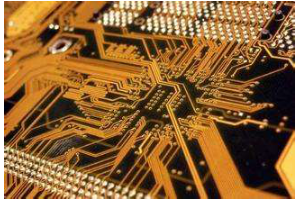
Intelligent wearable PCB
PCB material
PCB is generally composed of laminations, which may be made of fiber reinforced epoxy resin (FR4), polyimide or Rogers materials or other laminated materials. The insulating materials between different layers are called semi curing sheets.
Intelligent wearable devices require high reliability, so when teachers are faced with the choice of using FR4 (PCB manufacturing material with the highest cost performance) or more advanced and expensive materials, this will become a problem.
If the application requires high-speed and high-frequency materials, FR4 may not be the best choice. The dielectric constant (Dk) of FR4 is 4.5, that of the more advanced Rogers 4003 series materials is 3.55, and that of the brother Rogers 4350 series is 3.66.
Lamination diagram of multilayer circuit board, FR4 material, Rogers 4350 and core layer thickness.
The dielectric constant of a PCB stack refers to the ratio of the capacitance or energy between a pair of conductors near the stack and the capacitance or energy between the pair of conductors in vacuum. In high frequency, it is better to have very small loss. Therefore, Roger 4350 with dielectric coefficient of 3.66 is more suitable for higher frequency applications than FR4 with dielectric constant of 4.5.
Normally, the number of PCB layers used for intelligent wearable devices ranges from 4 to 8. The principle of layer construction is that if it is an 8-layer PCB, it should be able to provide enough layers and power supply layers and clamp the wiring layer in the middle. In this way, ripple effect in crosstalk can be kept to a minimum and electromagnetic interference can be significantly reduced ().
In the circuit board layout design phase, the layout scheme is generally to place large blocks of layers close to the power distribution layer. This can form a very low ripple effect, and the system noise can be reduced to almost zero. This is particularly important for the RF subsystem.
Compared with Rogers materials, FR4 has a higher dissipation factor (Df), especially at high frequencies. For the FR4 stack with higher performance, the Df value is about 0.002, which is an order of magnitude better than the common FR4 stack. However, Rogers has a stack of 0.001 or less. When FR4 materials are used in high-frequency applications, there will be a significant difference in insertion loss. Insertion loss is defined as the power loss of signal transmitted from point A to point B when FR4, Rogers or other materials are used.
Manufacturing problems
Smart wearable PCB requires stricter requirements, which is an important factor for smart wearable devices. PCB impedance matching can generate cleaner signal transmission. Earlier, the standard tolerance for signal carrying routing was ± 10%. This indicator is obviously not good enough for today's high-frequency high-speed circuits. The current requirement is ± 7%, or even ± 5P% or less in some cases. This parameter and other variables will seriously affect the manufacturing of these smart wearable PCBs with particularly strict impedance control, thereby limiting the number of businesses that can manufacture them.
The dielectric constant tolerance of the layers made of Rogers ultra-high frequency materials is generally kept at ± 2%, and some products can even reach ± 1%. In contrast, the dielectric constant tolerance of FR4 layers is as high as 10%. Therefore, comparing the two materials, it can be found that Rogers' insertion loss is particularly low. Compared with the traditional FR4 material, the transmission loss and insertion loss of Rogers stack are half lower.
In most cases, cost is the most important. However, Rogers can provide relatively low loss high-frequency stack performance at an acceptable price. For commercial applications, Rogers and FR4 based on epoxy resin can be made into a mixed PCB, some of which are made of Rogers material, and others are made of FR4.
Frequency is the primary consideration when selecting Rogers stacks. When the frequency exceeds 500MHz, Rogers materials are preferred, especially for RF/microwave circuits, because these materials can provide higher performance when the wiring above is strictly impedance controlled.
Compared with FR4 material, Rogers material can also provide lower dielectric loss, and its dielectric constant is stable in a wide frequency range. In addition, Rogers materials can provide the ideal low insertion loss performance required by high-frequency operation.
The coefficient of thermal expansion (CTE) of Rogers 4000 series materials has excellent dimensional stability. This means that compared with FR4, when PCB undergoes cold, hot and very hot reflow cycles, the thermal expansion and cold contraction of PCB can be kept at a stable limit under higher frequency and higher temperature cycles.
In the case of mixed layers, Rogers and high-performance FR4 can be easily mixed together using the general PCB manufacturing process technology, so it is relatively easy to achieve high manufacturing yield. Rogers lamination does not require a special through hole preparation process.
Ordinary FR4 cannot achieve very reliable electrical performance, but high-performance FR4 materials do have good reliability characteristics, such as higher Tg, still relatively low cost, and can be used for a wide range of applications, from simple audio design to complex microwave applications.


Just upload Gerber files, BOM files and design files, and the KINGFORD team will provide a complete quotation within 24h.