
Professional PCB manufacturing and assembly
Building 6, Zone 3, Yuekang Road,Bao'an District, Shenzhen, China
+86-13410863085Mon.-Sat.08:00-20:00

Precautions in PCB design
Scheme design is the preparatory work It is often seen that beginners draw PCB boards directly to save time This is an unworthy loss For simple boards, if you are proficient in this process, you may want to skip it But for beginners, you must follow this process. On the one hand, you can form good habits. On the other hand, it is the only way to avoid mistakes in complex circuits
When drawing diagrams and designing hierarchies, it is important to note that each file should be connected as a whole, which is also of great significance for future work. Due to software differences, some software may appear to be connected but not actually (in terms of power efficiency). If you do not use the relevant test tools for testing, it is too late to know when the board will be ready if problems occur. In retrospect, I have repeatedly stressed the importance of being orderly, hoping to attract everyone's attention. The schematic diagram is based on the design project. As long as the power connection is correct, there is nothing to say. Now we will focus on the problems in the specific plate making program.
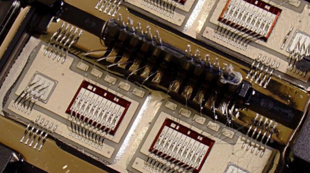
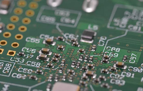
PCB board

1. Create physical boundary
The closed physical boundary is the basic platform for future component layout and routing, and also serves as a constraint for automatic layout Otherwise, the components from the schematic will be overwhelmed But you must pay attention here, otherwise, the installation problem will be very troublesome in the future Arc can also be used at corners to avoid sharp corner scratching and reduce pressure In the past, one of my products always had a case where the PCB surface shell was broken during transportation After switching to arc, it is OK
2. Introduction to Components and Networks
It should be very simple to draw components and networks into a well drawn framework, but problems often occur here. You must carefully follow the prompts to solve them one by one, otherwise, more effort will be spent in the future. Generally speaking, the problems here are as follows: the package form of the component cannot be found, the network problem of the component, and the unused component or pin. It is suggested that these problems can be solved quickly.
3. Layout of components
The layout and wiring of components have a great impact on product life, stability and electromagnetic compatibility, so special attention should be paid. In general, the following principles should be followed:
3.1 Place an order
First, place the components in fixed positions related to the structure, such as power sockets, indicator lights, switches, connectors, etc. After placing these components, use the software's lock function to lock them so that they do not move incorrectly in the future. Then special components and large components, such as heating elements, transformers, ICs, etc., are placed on the line. Place small equipment.
3.2 Pay attention to heat dissipation
The layout of components shall also pay special attention to heat dissipation. For high-power circuits, heating elements such as power tubes and transformers should be placed in a distributed layout as far as possible for heat dissipation. Do not concentrate them in one place, and do not put high capacitance too close to prevent premature aging of electrolyte.
4. Wiring
Wiring principle: wiring knowledge is very advanced, everyone will have their own experience, but there are still some common principles.
1) The trace of high-frequency digital circuit should be thinner and shorter.
2) Attention shall be paid to the isolation between high current signal, high voltage signal and high voltage signal, And small signal (The isolation distance is related to the withstand voltage to be borne. Generally, at 2kv, the distance between circuit boards is 2mm, and the ratio is calculated on this basis. For example, if the 3kv withstand voltage test is to be borne, the distance between high and low voltage lines should be greater than 3.5mm. In many cases, in order to avoid creepage, the high voltage and low voltage lines should also be made between the high voltage and low voltage lines on the slot printed circuit board.)
3) When wiring on two panels, the conductors on both sides shall be perpendicular, inclined or bent to each other to avoid being parallel to each other and reduce parasitic coupling; The printed wires used as circuit input and output shall avoid adjacent wires as much as possible. Parallel To avoid reverberation, add a ground wire between these wires.
4) The wiring angle should be as large as 90 degrees as possible, avoiding angles below 90 degrees, and using 90 degrees as little as possible.
5) Same as the address line or data line, the length difference of the line should not be too large, otherwise, the short line should be compensated by artificially bending the curve
6) The trace shall be located on the welding surface as much as possible, especially on the PCB with through-hole process
7) Minimize the use of vias and jumpers
8) The single panel pad must be large, the wires connected to the pad must be thick, and tears must be dropped as much as possible. Generally, the quality of single panel manufacturers is not very good, otherwise welding and rework problems will occur.
9) Large area copper plating shall adopt reticular structure to prevent bubbles and bending of circuit board due to thermal stress during wave soldering. However, in special cases, the flow direction and size of GND should be considered, and it cannot be simply filled with copper foil. Here's the thing, but you need to go this way
10) Components and wiring should not be placed too far away. Generally speaking, single panel is mostly cardboard, which is easy to break after being stressed. If components are connected or placed on edges, they are affected.
11) The convenience of production, commissioning and maintenance must be considered
For analog circuits, it is very important to deal with grounding problems. Noise generated on the ground is usually unpredictable, but once it occurs, it will bring great trouble and should be avoided. For the power amplifier circuit, due to the amplification of the later stage, very small ground noise will have a significant impact on the sound quality; In a high-precision A/D conversion circuit, if there is a high frequency component on the ground wire, there will be a certain temperature drift, which will affect the sound quality. The amplifier works. At this time, decoupling capacitors can be added at four corners of the circuit board. One foot is connected to the ground on the circuit board, and the other foot is connected to the mounting hole (connected to the main housing through screws). In this way, this component can be considered, and the amplifier and AD are also stable. In addition, in the current situation that people pay more attention to environmental protection products, electromagnetic compatibility is more important. Generally speaking, there are three types of electromagnetic signals: signal source, radiation and transmission line. Crystal oscillator is a common high-frequency signal source. The energy value of each harmonic in the power spectrum of crystal oscillator will be significantly higher than the average value. The feasible method is to control the amplitude of the signal, ground the crystal oscillator housing, mask the interference signal, and use special filtering circuits and equipment. It should be noted that the serpentine trajectory has different functions due to different applications. It is used for some clock signals in the computer motherboard, such as pick and AGP Clk. It has two functions: 1) impedance matching and 2) filter inductance. For some important signals, such as hub connections in the Intel hub architecture, there are a total of 13, and the frequency can reach 233MHz. The required length must be strictly equal to eliminate the hidden danger caused by time delay. At this point, serpentine cabling is the solution. In general, the line spacing of the serpentine track is>=2 times the line width; If it is in an ordinary PCB board, it can also be used as an inductive coil for radio antennas in addition to the function of filter inductance.
5. Perfect adjustment
After the wiring is completed, it is only necessary to make some adjustments to the text, single component and trace, and use copper (this work should not be done too early, or it will affect the speed and cause trouble to the wiring). It is also convenient for production, debugging and maintenance. Copper deposition usually refers to filling the blank area left after wiring with a large area of copper foil. You can lay GND copper foil or VCC copper foil (but in case of short circuit, this will easily burn the equipment and ground it, unless you must use it to add copper foil. The conductive area of large power supply is connected to VCC to withstand large current). Grounding wrapping usually refers to wrapping a bundle of signal wires with special requirements with two ground wires (TRAC) to prevent interference or interference from others. If copper is used instead of ground wire, attention must be paid to whether the whole grounding is connected, the current size, flow direction, and whether there are special requirements to ensure that unnecessary errors are reduced.
6. Check and verify the network
Sometimes due to misoperation or negligence, the network relationship of the drawn circuit board is different from the schematic diagram. At this point, it is necessary to check. This, after painting, do not rush to the plate maker, first check, and then carry out the follow-up work.
7. Use the analogy function
After completing these tasks, if time permits, software analogy can be conducted Especially for high-frequency digital PCB, some problems can be found in advance, which greatly reduces the workload of future debugging
The above is the explanation given by the editor of pcb circuit board company. If you want to know more about PCBA, you can go to our company's home page to learn about it. In addition, our company also sells various circuit boards,
High frequency circuit board and SMT chip are waiting for your presence again.


Just upload Gerber files, BOM files and design files, and the KINGFORD team will provide a complete quotation within 24h.