
Professional PCB manufacturing and assembly
Building 6, Zone 3, Yuekang Road,Bao'an District, Shenzhen, China
+86-13410863085Mon.-Sat.08:00-20:00

1、, Kingford SMT processing plant how to reduce proofing time?
Want to reduce the time of the SMT proofing, we don't waste time on something else, before making a proofing work must be carefully to understand the needs of the customer, correct understanding from the perspective of several different aspects, this is our premise and basis to reduce the time spent, no one in the process of doing this job, We must have a correct understanding of some of the situations, which is the premise for us to better complete the whole proofing work.
For any person, since we want to reduce the time of smt patch proofing, we should also do some related plans in advance, so as to be more standardized, and effectively avoid many other problems in the process of doing, so that we can avoid some detours in the process of manufacturing.
So when doing the design scheme should be timely to do some standardization, such as the heat dissipation of the line hole, specific reservation, and some marked position, may just be the design of planning, must write the corresponding parameters, so that you can reduce the use of time.
Since SMT proofing of work to do, we should also do some appropriate planning of the work ahead of time, and can also have the correct understanding, to the number of specific number if the first plan is too large, it can lead to cost is higher, but also should try to do more out when doing the proofing.
Because this may bring us more protection, so no matter who is doing, we should actively consider these actual situations, because this point can bring us more role and significance, but also can guarantee the subsequent use of the situation.

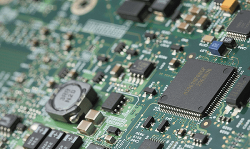
2、, the key equipment in SMT production
smt SMT machine is a key and complex equipment in SMT production. smt mounter has been developed from the early low speed mechanical mounter to the high speed optical center mounter, and to the multi-function, flexible connection modular development.
A, classification,
1. According to the speed, it is divided into medium speed patch machine, high speed patch machine and super high speed patch machine.
2. According to the function, it is divided into: high speed/ultra-high speed mounter: mainly with the mounter component as the main body, there are not many varieties of the mounter device;
3. According to the degree of automation is divided into full automaton SMT machine: most of the SMT machine is this kind of machine.
4. According to the way of placement, it is divided into sequential placement machine: it is in accordance with the order of the components are attached to the PCB, usually seen is this kind of placement machine. Simultaneous laminator: WITH a special hopper for placing cylindrical components, all components can be mounted on the corresponding pads of PCB in one action. When the product is replaced, all the materials are replaced completely, which is rarely used. Simultaneous on-line laminating machine: It is composed of a plurality of laminating pieces, which can mount a PCB at the same time in turn.
2、, precision SMT machine process
1. Place the circuit board with components on a tray perpendicular to the bottom of the camera.
2. Turn on the switch of the mounting machine
3. Lift up the circuit board with components and attach the original to the suction cup of the vacuum pen.
4. Place the printed PCB to be welded on a tray perpendicular to the bottom of the camera.
5. Adjust the high and low knobs of the vacuum suction pen to move it down until it is 1-2 cm away from the printed circuit board.
6. Open the display switch and observe on the display. Adjust the tray knob to make the IC chip pin completely coincide with the solder pad corresponding to the printed circuit board to be welded.
7. Place the IC chip on the vacuum nozzle vertically and gently onto the solder pad corresponding to the printed circuit board.
8. Because the suction nozzle has not been powered off, it is not possible to remove the suction nozzle immediately at this time. Turn off the switch to stop the suction nozzle from working, gently remove the vacuum suction nozzle in the vertical direction, and mount it.
SMT management How to manage smt pipeline
Oct 31,2022


Just upload Gerber files, BOM files and design files, and the KINGFORD team will provide a complete quotation within 24h.