
Professional PCB manufacturing and assembly
Building 6, Zone 3, Yuekang Road,Bao'an District, Shenzhen, China
+86-13410863085Mon.-Sat.08:00-20:00

Experience of Reducing Noise and Electromagnetic Interference in PCB Technology
1. Series resistance can be used to reduce the jump rate of upper and lower edges of control circuit.
2. Try to make the potential around the clock signal circuit close to zero, and use the ground wire to circle the clock area. The clock wire should be as short as possible.
3. The I/O drive circuit shall be close to the edge of the printed board as far as possible.
4. The unused gate circuit output terminal shall not be suspended. The unused op amp positive input terminal shall be grounded, and the negative input terminal shall be connected to the output terminal.

5. Try to use 45 ° polyline instead of 90 ° polyline to reduce the external transmission and coupling of high-frequency signals.
6. The clock line perpendicular to the I/O line has less interference than that parallel to the I/O line.
6. The pins of PCB components should be as short as possible.
8. Do not run wires under the quartz crystal oscillator or the components that are particularly sensitive to noise.
9. The ground wire around the weak signal circuit and low-frequency circuit shall not form a current loop.
10. If necessary, add ferrite high-frequency choke to the line to separate signal, noise, power and ground.
A through-hole on the PCB causes a capacitance of about 0.6pF; The packaging material of an integrated circuit itself causes the distributed capacitance of 2pF~10pF; A connector on a circuit board, 520 μ Distribution inductance of H; A dual in-line 24 pin integrated circuit socket, introducing 4 μ H~18 μ The distributed inductance of H.
Anti interference Design of Digital Circuit and Single Chip Microcomputer
In the design of PCB electronic system, in order to reduce detours and save time, anti-interference requirements shall be fully considered and met, and anti-interference remedial measures shall be avoided after the design is completed. There are three basic elements to form interference:
(1) Interference source refers to the element, equipment or signal generating interference, which is described in mathematical language as follows: du/dt, di/dt
Fang is the interference source. For example, lightning, relay, silicon controlled rectifier, motor, high-frequency clock, etc. may become interference sources.
(2) Propagation path refers to the path or medium through which interference propagates from the interference source to the sensitive device. The typical interference propagation path is through
Conductor conduction and space radiation.
(3) Sensitive devices refer to objects that are easy to be interfered with. For example: A/D, D/A converter, single-chip microcomputer, digital IC, weak signal amplification
And so on.
The basic principle of anti-interference design of PCB is to restrain the interference source, cut off the interference propagation path, and improve the anti-interference performance of sensitive devices.
(Similar to the prevention of infectious diseases)
1 Suppress interference sources
Suppressing interference sources is to reduce du/dt, di/dt of interference sources as much as possible. This is the most priority and important principle in the anti-interference design of PCB, which can often achieve twice the result with half the effort. The du/dt of the interference source is reduced mainly by paralleling capacitors at both ends of the interference source. The di/dt of the interference source is reduced by adding inductance or resistance in series and freewheeling diode in the interference source circuit.
Common measures to suppress interference sources are as follows:
(1) The relay coil is added with a freewheeling diode to eliminate the back EMF interference generated when the coil is disconnected. Only adding freewheeling diode will delay the disconnection time of the relay, and the relay can act more times in a unit time after adding voltage stabilizing diode.
(2) Both ends of relay contact are connected with spark suppression PCB circuit in parallel (generally RC series circuit, resistance is generally selected from K to tens of K, capacitance is selected from 0.01uF) to reduce the impact of electric spark.
(3) Add a filter circuit to the motor, and pay attention to the capacitor and inductor leads should be as short as possible.
(4) Each IC on the PCB shall be connected to 0.01 in parallel μ F~0.1 μ F High frequency capacitor to reduce the influence of IC on power supply. Pay attention to the wiring of high-frequency capacitor. The wiring should be close to the power terminal and as short as possible. Otherwise, the equivalent series resistance of the capacitor will be increased, which will affect the filtering effect.
(5) Avoid 90 degree polyline during PCB wiring to reduce high-frequency noise emission.
(6) The RC suppression circuit is connected at both ends of the thyristor in parallel to reduce the noise generated by the thyristor (when the noise is serious, the thyristor may be broken down).
According to the propagation path of interference, it can be divided into conducted interference and radiated interference.
The so-called conducted interference refers to the interference transmitted to the sensitive device through the wire. The frequency band of high-frequency interference noise is different from that of useful signal. The transmission of high-frequency interference noise can be cut off by adding a filter on the wire. Sometimes, isolation optocouplers can be added to solve this problem. Power supply noise is the most harmful, so special attention should be paid to handling. The so-called radiation interference refers to the interference transmitted to sensitive devices through space radiation. The general solution is to increase the distance between the interference source and the sensitive device, isolate them with a ground wire and add a shield on the sensitive device.
This paper is about the experience of PCB anti-interference design for reducing noise and electromagnetic in PCB technology
Removal method of multi pin IC of circuit board
Oct 26,2022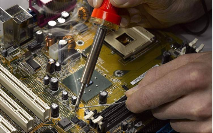


Just upload Gerber files, BOM files and design files, and the KINGFORD team will provide a complete quotation within 24h.