
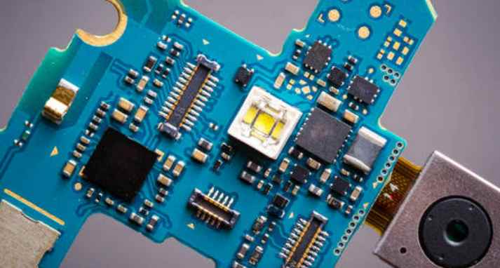
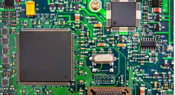
Professional PCB manufacturing and assembly
Building 6, Zone 3, Yuekang Road,Bao'an District, Shenzhen, China
+86-13410863085Mon.-Sat.08:00-20:00

In pieces in pieces
The solder pad is the soldermask, which refers to the part of the board to be covered with green oil. In fact, the solder mask uses a negative output, so when the shape of the solder mask is mapped to the board, it is not green oil solder, but exposed copper. Usually in order to increase the thickness of copper, the welding resistance layer is marked to remove green oil, and then tin is added to increase the thickness of copper wire.
In pieces in pieces
Welding resistance layer requirements
In pieces in pieces
Choke layers are important in controlling weld defects in reflow welding, and PCB designers should minimize spacing or air gaps around the pads.
While many process engineers would prefer a solder shield to separate all pad features on the plate, pin spacing and pad size for closely spaced components will require special consideration. While non-zoned solder layer openings or Windows on the four sides of the qfp may be acceptable, controlling the tin bridge between the element pins may be more difficult. For bga solder resist layer, many companies provide a kind of resistance welding layer, it does not touch pad, but to cover any characteristics of bonding pad, in order to prevent the solder bridge. Most of the surface mount PCB for resistance welding layer, but resistance welding layer coating, if the thickness is greater than 0.04 mm, may affect the application of solder paste. Surface-mounted PCBS, especially those using closely spaced components, require a low photoresist layer.
In pieces in pieces
Job production
In pieces in pieces
Solder resistance materials must be used by liquid wet process or dry film lamination. Dry film solder resistance material is available in 0.07-0.1mm thicknesses and is suitable for some surface mount products, but this material is not recommended for close spaced applications. Few companies offer dry films thin enough to meet tight spacing standards, but several companies offer liquid sensitive solder resistance materials. Normally, the choke opening should be 0.15mm larger than the pad. This allows a 0.07mm gap on the side of the pad. Low-profile liquid photosolder materials are economical and are often specified for surface mount applications, providing precise feature sizes and clearances.
In pieces in pieces
Introduction of welding aid layer

In pieces in pieces
The welding aid layer is used for patch encapsulation, corresponding to the patch component pad. In SMT processing, a steel plate is usually used to punch holes on the PCB corresponding to the solder pad of components, and then the solder paste on the steel plate. When the PCB is under the steel plate, the solder paste leaks down, which means that each solder pad can be stained with solder, so usually the solder resistance layer cannot be larger than the actual size of the solder pad, and it is better to be less than or equal to the actual size of the solder pad.
The required level and sticker elements are almost the same, and the main requirements are as follows:
1. BeginLayer: ThermalRelief and AnTIPad should be 0.5mm larger than the actual size of the regular pad
2. EndLayer: ThermalRelief and AnTIPad should be 0.5mm larger than the actual size of the regular pad
3. DEFAULTINTERNAL: Intermediate layer
The role of solder shield and solder aid
In pieces in pieces
Solder resistance layer is mainly to prevent PCB copper foil directly exposed to the air, play a protective role.
The welding layer is used to make steel mesh for the steel mesh factory, and the steel mesh can be accurately placed on the solder paste to be welded on the patch pad.
In pieces in pieces
Difference between PCB welding aid layer and welding resistance layer
In pieces in pieces
The two layers are used for soldering on tin, not a tin, a green oil; Instead:
1, resistance welding layer is on the whole piece of resistance welding green oil window, the purpose is to allow the welding;
2. By default, green oil should be applied to areas without solder resistance layer;
3. Welding aid layer is used for patch encapsulation.
Wiring technology for PCB high-speed signal circuit design skills Sharing
Source: PCB Date: 2020-07-28 Page Views: 206
PCB board design is a required course for electronic engineers, and to design a perfect PCB board is not as easy as it looks. A perfect PCB board not only needs to do the component selection and setting is reasonable, but also needs to have good signal conduction performance. This paper will introduce and share the knowledge of wiring skills in PCB high-speed signal circuit design in detail, hoping to be helpful to your work.
Reasonable use of multilayer board for PCB routing
In the actual design process of PCB board, most engineers will choose to use multilayer board to complete high-speed signal wiring work, this kind of multilayer board is not only an essential component, but also an effective means to help engineers reduce circuit interference. In the use of multilayer board to complete PCB high-speed signal circuit design, engineers need to choose a reasonable number of layers to reduce the size of the printed board, make full use of the intermediate layer to set shielding, realize the nearby grounding, can effectively reduce the parasitic inductance, shorten the length of signal transmission, reduce the cross interference between signals and so on. All these methods are very beneficial to the reliability of high speed circuits.
In addition to the above mentioned methods of using multilayer boards to improve the reliability of PCB signal transmission, some authoritative data shows that the noise of four-layer boards is 20dB lower than that of dual panels when the same material is used. The less the lead bend, the better, the best use of full line, the need for turning, can be used 45 degrees fold line or arc turning, can reduce the high-speed signal external emission and mutual coupling, reduce signal radiation and reflection.
The shorter the leads between the pins of a high-speed circuit device, the better
In the process of PCB high-speed signal circuit design and wiring, engineers need to shorten the lead between the pins of high-speed circuit devices as much as possible. The longer the lead, the larger the distributed inductance and capacitance, which will cause reflection and oscillation in the high-speed circuit system.
In addition to shortening the lead between pins of high-speed circuit components as much as possible, in the process of PCB wiring, the lead layer alternations between pins of various high-speed circuit components should be minimized, that is, the fewer holes used in the process of component connection, the better. Typically, a pass hole brings about 0.5pF of distributed capacitance, which results in a significant increase in circuit delay. At the same time, high-speed circuit wiring should pay attention to the "cross interference" introduced by short distance parallel routing of signal lines. If parallel distribution cannot be avoided, a large area of "ground" can be arranged on the opposite side of parallel signal lines to reduce interference. At two adjacent layers, the direction of the cables must be perpendicular to each other.
Cooling tips for PCB circuit boards
Apr 12,2023


Just upload Gerber files, BOM files and design files, and the KINGFORD team will provide a complete quotation within 24h.