
Professional PCB manufacturing and assembly
Building 6, Zone 3, Yuekang Road,Bao'an District, Shenzhen, China
+86-13410863085Mon.-Sat.08:00-20:00

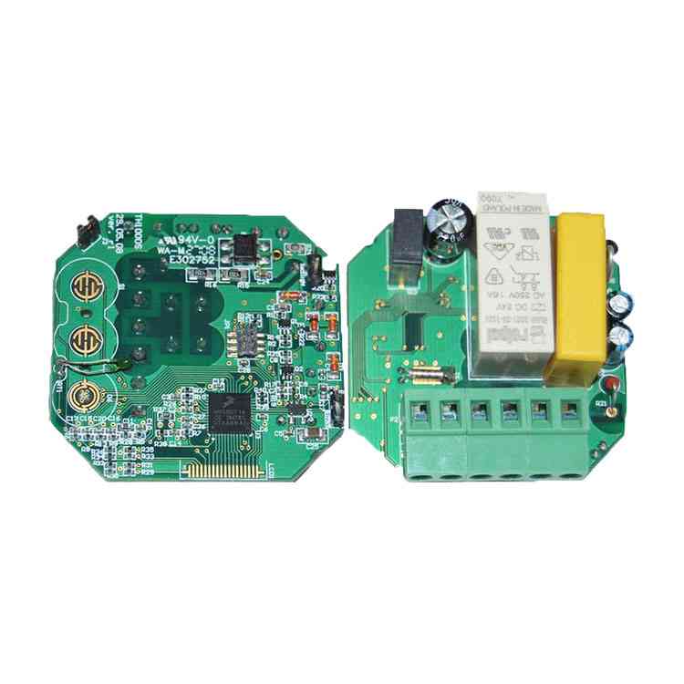
1. Most circuit boards are prone to bending and warping during reflow soldering. If serious, it may even lead to blank welding of parts, tombstones, etc. How do we prevent PCB boards from bending and warping in reflow soldering? Let Kingford find out for you.
PCB circuit board deformation hazard
An uneven PCB board on an automatic surface mounting line will result in incorrect positioning, inability to insert or place components on holes and surface mounting pads in the board, and even damage the automatic inserter. After welding, the installed component is bent, and the legs of the component are difficult to cut neatly. The board does not fit into a slot in the case or machine, making it difficult for the assembly plant to reach the board. The current surface mounting technology is developing towards high precision, high speed and intelligence, which requires higher flatness for PCB boards used in various components.
Cause analysis of PCB deformation
1. Uneven areas of the copper plane on the circuit board will exacerbate the bending and warping of the circuit board.
Typically, large areas of copper foil are designed to ground the circuit board. Sometimes, Vcc layers are also designed with large areas of copper foil. When these large areas of copper foil can not be evenly distributed on the same circuit board, it will cause the problem of uneven heat absorption and heat dissipation speed. Of course, PCB boards also expand and contract. If expansion and contraction cannot be caused at the same time, different stresses and deformation will be caused. At the upper limit of Tg values, the plate will begin to soften, causing permanent deformation.
2. The weight of the PCB board itself may also cause the board to sag and deform.
The refluxing furnace uses a chain to drive the circuit board in the refluxing furnace. That is, the two sides of the board are used as fulcrum to support the entire board. If the board has overweight parts, or the size of the board is too large, due to the number of the board itself, there will be a depression in the middle, causing the board to bend.
solution
1. Reduce the influence of temperature on the stress of PCB board.
Because temperature is the main source of plate stress, the occurrence of plate bending and warping can be greatly reduced simply by lowering the temperature of reflow welding or raising and cooling the plate temperature in the reflow furnace. However, other side effects may occur, such as short circuit of solder.
2. Use high Tg plates.
Tg is the glass transition temperature, the temperature at which a material changes from glass to rubber. The lower the Tg value, the faster the plate will begin to soften after entering the return furnace, and the longer it will take to become soft rubber. Of course, the deformation of the plate will become more serious. Using a plate with higher Tg can increase its ability to withstand stress and deformation, but the price of the material is relatively high.
3. Increase the thickness of PCB board
In order to make many electronic products thinner and thinner, the thickness of the board is kept at 1.0mm, 0.8mm or even 0.6mm. It is recommended to use a circuit board with a thickness of 1.6mm when it is not light. This can greatly reduce the risk of bending and deformation of the circuit board.
4, reduce the size of the circuit board and the number of puzzles
Since most reflow furnaces use chains to drive PCB boards forward, the larger circuit boards will sag in reflow furnaces due to their own weight. Therefore, please try to place the long edge of the circuit boards as the edge of the boards. Therefore, the sag deformation caused by the weight of the circuit boards can be reduced by reducing the chain of reflow furnaces. And it can reduce the number of problems. Low sag deformation
5. Use an oven tray to secure the fixture
If the above methods are difficult to achieve, a reflux carrier (template) should be used to reduce the amount of deformation. The reason reflow pallets reduce the bending and warping of the plate is that they are required for both thermal expansion and cold shrinkage. You can fix the board, wait until the temperature of the board is below the Tg value to start the re-hardening, and then you can keep the original size.
If a single pallet does not reduce the deformation of the PCB board, another cover must be added and the board must be clamped with an upper and lower pallet. This can greatly reduce the deformation of the circuit board through the reflux furnace.
6. Use router instead of V-Cut subroutine
Do not use V-Cut subroutine or reduce the depth of the V-Cut since V-Cut will destroy the structural strength of the board-to-board puzzle.

2. What is the stamp hole of pcb small board
The small board of the circuit board is divided into a small board according to customer requirements. Generally, however, the board will be placed with the board and the smaller of the multiple boards put together to form a large SET. In common production, however, board platting is used, and multiple boards and boards are grouped together to form large sets. The meaning of printed circuit board: on the one hand, convenient subsequent customers welding and paste circuit board; On the other hand, it can improve the utilization rate of the plate, thus reducing the production cost.
What is the stamp hole of pcb small board?
The minimum board size we can manufacture is 10mm x 10mm with a tolerance of +/- 0.1mm. However, individual size is not restricted. PCS and PCS are usually connected through punch holes. In the motherboard Mosaic, a rib connection is required between the small board and the small board. In order to facilitate cutting, a number of small holes are cut in the ribs, similar to the impression edge holes called impression holes.
As the products of each industry are different, the PCB board sizes used are also different. Some PCBS in the electronics industry are relatively small, and they are often designed as a patchwork method, which not only facilitates processing and production in electronics factories. It can also reduce the waste of circuit boards and reduce costs
What are the segmentation techniques of pcb plate?
Typically, PCBS can be assembled using either the die hole technique or the double-sided V slot splitting technique. When using punch holes, it should be noted that the edges should be evenly distributed on each plate to avoid PCB welding. Uneven force will cause deformation. The position of the embossed hole should be close to the inside of the PCB board to prevent residual burr on the embossed hole from affecting the customer's complete assembly. When using a double-sided V-groove, the depth of the V-groove should be controlled to approximately 1/3 (the sum of the two sides of the groove), and the groove size must be accurate and the depth uniform. Each small board in the PCB panel must have at least three positioning holes, 3≤ aperture ≤6mm, and no wiring or pasting is allowed within 1mm of the edge positioning holes. No large devices or protruding devices are allowed near the connection points between the outer panel frame and the inner panel, and between the small panel and the small panel. The distance between the components and the PCB should be greater than 0.5mm to ensure the normal operation of the cutting tools.
How to find holes in PCB board?
In order to facilitate the manufacture of the board and the processing of PCBA, PCB plate design requires positioning holes on the board. For the reference symbol of PCB board positioning and fine-spaced device positioning, in principle, QFPS with spacing less than 0.65 mm should be placed in their diagonal position; The positioning reference symbols for the sectional PCB subboard should be used in pairs and placed at opposite corners of the positioning element. Large components should have positioning posts or positioning holes, such as I/O ports, microphones, battery ports, microswitches, headphone ports, motors, etc.a
PCBA quality control in SMT plant
Feb 20,2023


Just upload Gerber files, BOM files and design files, and the KINGFORD team will provide a complete quotation within 24h.