
Professional PCB manufacturing and assembly
Building 6, Zone 3, Yuekang Road,Bao'an District, Shenzhen, China
+86-13410863085Mon.-Sat.08:00-20:00

In order to understand PCB, it is necessary to understand the production process of usually single-sided, double-sided printed circuit board and ordinary multilayer board, in order to deepen the understanding of it.

Single-side rigid printed board: → Single-side copper-covered plate → blanking → (brushing, drying) → drilling or punching → screen printing line anti-etching graphics or use dry film → curing inspection repair plate → etching copper → to resist printing material, drying → brushing, drying → screen printing solder graphics (commonly used green oil), UV curing → screen printing character marking graphics, UV curing → preheating, punching and shape → electrical opening, short circuit test → brushing and drying → Pre-coating welding anti-oxidant (dry) or tin-spraying hot air leveling → inspection of packaging → finished products leaving the factory.
Double-sided rigid printed board: → Double-sided copper clad plate → blanking → lamination → NC drilling through hole → inspection and deburring brush → electroless plating (through hole metalization) → (full plate plating thin copper) → inspection brush → screen printing negative circuit graphic, curing (dry film or wet film, exposure, development) → inspection and repair → line graphic plating → tin plating (nickel resistance/gold) → removing printing material (sensitive film) → etching copper → (tin removal) ) → Cleaning and brushing → screen printing solder resistance graphics commonly used thermal curing green oil (paste sensitive dry film or wet film, exposure, development, thermal curing, commonly used sensitive thermal curing green oil) → cleaning, drying → screen printing marking character graphics, curing → (spray tin or organic welding protection film) → shape processing → cleaning, drying → electrical on-off detection → inspection packaging → finished products.
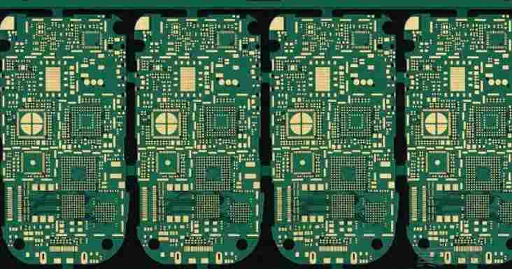
Process flow of through hole metallization Process for manufacture of multilayer plate → double-sided opening of inner copper clad plate → brushing → drilling positioning holes → sticking photoresist dry film or coating photoresist → exposure → developing → etching and removing film → inner coarsing and oxidizing → inner layer inspection → (outer single-sided copper clad plate circuit fabrication, B-step bonding sheet, plate bonding sheet inspection, drilling positioning holes) → lamination → number control drilling → Hole inspection → Pre-treatment and electroless copper plating → full plate plating of thin copper → coating inspection → Photoresistant dry plating film or coating of photoresistant plating agent → surface plate exposure → Developing and repairing → line graphic plating → plating of tin lead alloy or nickel/gold plating → Film removal and etching → Inspection → screen printing solder resistance graphics or photoresist welding graphics → printed character graphics → (hot air smoothing or organic soldering film) → numerical control Washing shape → cleaning and drying → electrical on-off detection → finished product inspection → packaging factory.
It can be seen from the process flow chart that the multilayer process is developed from the double face metallization process. In addition to the double-sided process, it also has several unique contents: internal interconnect of metallized holes, drilling and decontamination, positioning system, lamination, special materials.
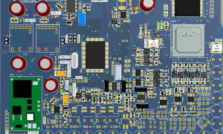
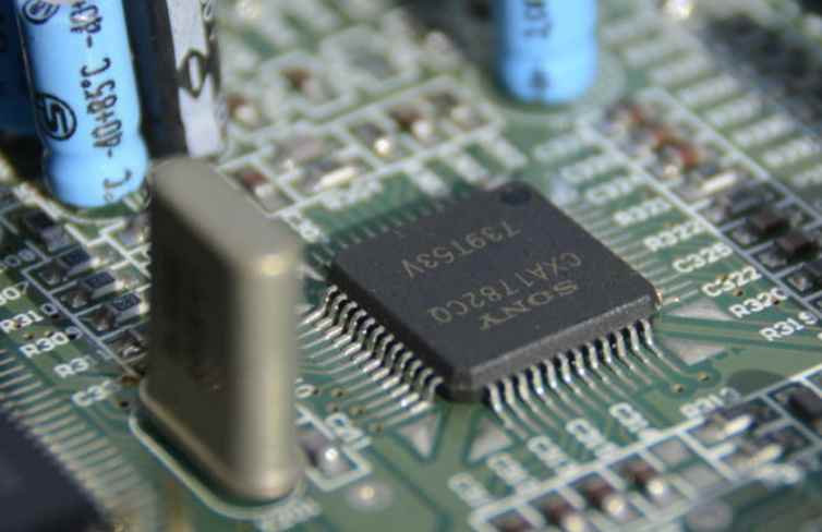
Our common computer board card is basically epoxy resin glass cloth based double-sided printed circuit board, one side is the plug-in component and the other side is the component foot welding surface, you can see that the solder joint is very regular, the component foot discrete welding surface of these solder joints we call it the welding pad. Why don't other copper wires figure on tin? Because in addition to the solder plate and other parts, the surface of the rest of the part has a layer of wave resistance welding film. Most of its surface solder resistance film is green, a few use yellow, black, blue, so in the PCB industry often welding resistance oil called green oil. Its function is to prevent the bridge phenomenon during wave welding, improve welding quality and save solder and so on. It is also a permanent protective layer for printed boards, which can prevent moisture, corrosion, mildew and mechanical abrasion. Viewed from the outside, the surface is smooth and bright green solder resistance film, for the film on the plate sensitive heat curing green oil. Not only the appearance is more beautiful, it is important to the high accuracy of the pad, thus improving the reliability of the solder joint.
As we can see from the computer board, there are three ways to install components. A driven plug-in installation process in which electronic components are inserted into the on-hole of the printed circuit board. In this way, it is easy to see that the double-sided printed circuit board has the following holes: one is the simple element insertion hole; The second is the component insertion and double-sided interconnection through hole; Third, the simple double-sided through hole; Four is the base plate installation and positioning hole. The other two mounting methods are surface mounting and direct chip mounting. In fact, chip direct installation technology can be considered as a branch of surface installation technology, it is the chip is directly glued to the printed board, and then connected to the printed board by wire welding method or carrier tape method, flip method, beam lead method and other packaging technology. The welding surface is on the component surface.


Just upload Gerber files, BOM files and design files, and the KINGFORD team will provide a complete quotation within 24h.