Overview of Mechanical Drilling Technology for Circuit Boards
Circuit board manufacturing, circuit board design and PCBA processing manufacturers will explain the overview of mechanical drilling technology for circuit boards
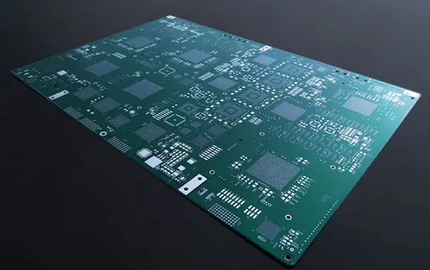
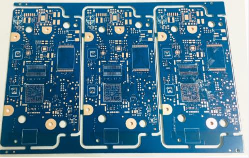
Mechanical drilling has always been the main way to form holes for circuit boards. The basic mechanical drilling processing procedure is: fix the circuit boards that have been pressed and checked at the benchmark position according to the allowable number of stacked pieces, place the lower backing plate under the upper cover of the protective cover plate, and then press the entire stack of circuit boards into the fixing holes of the drilling machine table with the rear pin to start drilling.
The drilling machine table uses NC data to control actions, including table movement, drill shaft up and down, high and low speed, drill needle exchange, etc. Digital controlled drilling machine processing requires mechanical origin. Place the whole stack of circuit boards on the relative position to drill holes with the designated hole diameter drill needle. After the drilling is completed and unloaded, carry out quantitative sampling inspection and send it to the next process for processing.

The key points of drilling operation are briefly described here:
1: Drilling stack
The purpose of stacking is to produce more circuit boards at the same time. The higher the number of stacked pieces of circuit boards is when drilling, but the size and accuracy of the aperture should still be taken into account. The smaller the aperture is, the fewer pieces can be stacked, and the higher the accuracy is required, the fewer pieces can be stacked.
When stacking, the cover plate and back plate will be placed at the top and bottom for different purposes. The purpose of the cover plate is to enable the drill needle to cut in smoothly and inhibit the occurrence of burrs. In addition, it can help the heat loss of the drill needle operation to improve the drilling quality. Most of them use aluminum alloy plates, aluminum plates, urea plates, synthetic plates, etc. The main purpose of the backplane is to serve as a sacrificial board, so that the drill needle can smoothly drill through the circuit board, avoid the drill needle from injuring the drilling machine platform, and reduce the hairiness generated at the bottom. The commonly selected materials are paper phenolic, wood pulp board, etc. However, no matter what kind of drilling auxiliary plate is selected, both quality and cost should be considered.
2: Drilling machine
The mechanical drilling machine has X and Y direction motion mechanisms, and has multiple drilling shafts on the same unit. Generally, the platform moves in the Y direction, while the fixed drilling shaft mechanism moves in the X direction. The drilling position is the cross coordinate formed by these two movements. As for Z-direction movement, it is connected by controlling the movement of special devices in the drill shaft up and down or in the shaft center. With XY motion and Z direction drill shaft motion, the drill needle at the front end is driven to drill holes of various diameters.
The motor driving the machine is a servo motor, which will follow the digital data to control the position and action. The number of axles of the machine mainly depends on the size of the circuit board produced and the number of product types. It is better to have fewer axles if the number is small and the number of products is large. It is better to have more axles if the number of products is small and the number of products is large.
In order to achieve the goal of high accuracy and small aperture, the drilling machine has put forward quite a number of solutions, such as: automatic induction of needle breakage, increasing drilling speed, improving chip removal design, increasing machine stability, etc., but it still needs to match the drilling needle material and appropriate drilling operation parameters.
3: Drill needle
The drill needle is the main consumable for circuit board hole forming. When using, the drill needle is installed on the drill shaft. With the help of the high speed provided by the drilling machine and the needle design, the appropriate cutting force can be produced to cut the composite material composed of resin, glass fiber and copper sheet of the circuit board, so as to achieve the goal of hole forming.
The design of the drill needle, such as the tip angle, spiral angle, the centrality of the drill blade, chip discharge and other shapes of the drill needle, will affect the drilling quality. In order to take account of the smoothness of the hole wall and reduce the amount of glue residue, the front end of the drill needle will adopt the method of reducing the diameter, which is called the Under Cut drill needle. In this way, better drilling results can be obtained.
In addition, when the drill needle is used, it must cut some hard materials such as glass fiber or ceramic filler, which will make the drill needle easy to wear. Therefore, at present, tungsten carbide superhard alloy is mostly used, or the proportion is adjusted to increase wear resistance and toughness, so as to improve the service life.
4: Post treatment and inspection
The drilled products are unloaded from the drilling machine and disassembled. Before they are sent out of the manufacturing process, the hole quality must be checked. The inspection items include: hole location, hole diameter, number of holes, etc. As for missing drilling, the spot check method and working negative film comparison can be used to confirm. At present, there are automatic hole position and hole diameter inspection machines, which can use the data provided by CAD system for image comparison, and it is easy to find the problem.
As for the visual inspection of the board surface, it is necessary to visually inspect the scratches and other damages caused during the operation. Although the state in the hole is not easy to be observed by the naked eye, there are 3D microscopes available for 360 degree observation in the hole. PCB manufacturers, PCB designers and PCBA processors will give you an overview of PCB mechanical drilling technology.


