
Professional PCB manufacturing and assembly
Building 6, Zone 3, Yuekang Road,Bao'an District, Shenzhen, China
+86-13410863085Mon.-Sat.08:00-20:00

The growth of the demand for portable products has promoted the continuous development of PCB from single-sided to double-sided, multi-layer, flexible and rigid flex composite boards, and also to high-precision, high-density and high reliability.

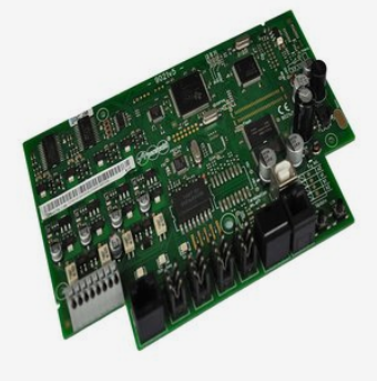
The base material of flexible circuit board (FPC board) is copper, so it is necessary to cover the circuit with a layer of covering film. The covering film material is generally polyimide. The thermosetting adhesive closely combines the covering film with the circuit board under high temperature, and the pressing plays a protective role on the surface of the circuit board. In the later stage of FPC board production, the shape needs to be processed. There is a row of plugs at the shape for connection with other electronic products. The reliability of PCB connection is stricter and higher for laser cutting accuracy.
At present, the method of batch processing FPC shape is blanking, and small batch FPC and FPC samples are mainly processed by laser cutting. Up to now, many manufacturers at home and abroad have developed UV laser cutting machines to make FPC samples. However, the commonly used cutting methods for FPC board plug shape: cursor point recognition method and character recognition method have not been reported in literature, and this method makes the operation of FPC board laser cutting more convenient and simple, and the cutting accuracy is also higher.
In this paper, through the production process of high-precision FPC board, in order to solve the problem of FPC board cutting deviation caused by expansion and contraction, the existing laser processing equipment is used, and the method of CCD identification of new plug edge is used to compensate the PCB size with large expansion and contraction deformation, and control the contour cutting within the accuracy requirements.
FPC Board Production Process and Shrinkage Principle
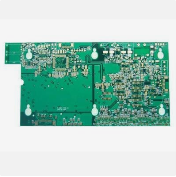
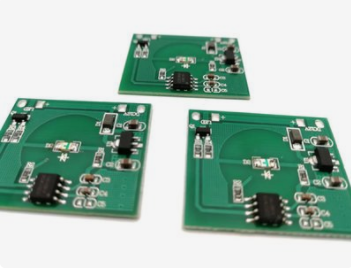
FPC circuit boards are mainly divided into single-sided, double-sided and multi-layer circuit boards. Double sided circuit boards are products developed from single panel
FPC board is mainly made of flexible copper clad laminate, protective film and polyimide reinforcing film.
Each process of FPC board production process will affect the expansion and contraction of the circuit board shape. The reason is that for the circuit board composed of flexible copper clad plate, polyimide and polyimide reinforcing film, the material temperature needs to be raised to above 170 ℃ during the lamination process. After cooling, internal stress occurs due to the difference in the expansion and contraction coefficients of copper and polyimide, which destroys the material balance force, shrinks and deforms the base material, and distorts the base material circuit diagram, It causes uneven expansion and contraction of FPC circuit board.
Uneven expansion and contraction of FPC board easily lead to the failure to meet the requirements of contour machining accuracy. In this paper, the profile laser cutting technology is used to measure the cutting deviation value of different expansion and contraction rates of the circuit board, draw the expansion and contraction precision curve of laser cutting, and then through the expansion and contraction precision curve, for the FPC board with large expansion and contraction rates, the new CCD reference point identification technology is used to correct the distortion of the FPC board, so as to improve the processing accuracy of the FPC board plug.
Experimental materials and equipment
10 FPC boards, ASIDA JG13 UV laser cutting machine, image projector (anime)
Experimental methods and data
First, measure the cutting accuracy of the laser equipment to determine whether the equipment meets the design accuracy requirements. Then select and cut several kinds of PCB with expansion and contraction rate, measure its cutting accuracy, and draw the curve of expansion and contraction rate and cutting accuracy.
Accuracy test of equipment
Test the running state and cutting accuracy of the equipment before cutting.
Measurement method: measure the distance from the plate to the edge, and then subtract the corresponding theoretical value to obtain the deviation value.
Cutting accuracy of different expansion and contraction templates
In the process of PCB production, the expansion and contraction deformation of the sample plate is caused by the reasons of splicing, electroplating, laminating and high and low temperature difference. The laser equipment itself makes appropriate compensation for the FPC board's expansion and contraction, but when the FPC board's expansion and contraction deformation is too large, it is impossible to control the cutting profile accuracy within the customer's requirements.
In order to measure the cutting accuracy of FPC boards with different expansion and contraction rates, seven kinds of circuit board materials with expansion and contraction rates of 0.1 ‰, 0.2 ‰, 0.5 ‰, 0.8 ‰, 1.0 ‰, 2.0 ‰ and 3.0 ‰ are selected respectively. After positioning, the shape is cut by laser, and then the cutting size is measured by anime method. Compared with the theoretical figure value, the deviation value is calculated, and then the average deviation value and variance are calculated.
The curve diagram of FPC board expansion and contraction rate and cutting accuracy shows that when the expansion and contraction rate is less than 0.8 ‰, the cutting accuracy fluctuates within ± 0.05mm. With the increase of the shrinkage rate, the average cutting deviation and variance increase. When the shrinkage rate is greater than 0.8 ‰, the cutting accuracy cannot meet the customer's requirements of ± 0.05mm.
The shrinkage rate is greater than 0.8 ‰, the average cutting deviation is greater than 0.020mm and the variance is greater than 0.025mm. This shows that the cutting accuracy of FPC board cannot meet the accuracy requirement of ± 0.05mm of the profile after the rise and fall rate exceeds 0.8 ‰.
It is a difficult problem for laser cutting to control the cutting accuracy of FPC boards with a shrinkage rate greater than 0.8 ‰ within ± 0.05mm. It has been reported in domestic literature that software algorithm theory is used to compensate PCB deformation to improve cutting accuracy, but there is no report on the measured cutting accuracy data.
Cutting Technology of FPC Board with a Shrinkage Rate greater than 0.8 ‰
According to literature reports and the quality requirements of circuit board manufacturers, the key dimensions of FPC board plugs are the plug size and the distance from the plug to the board edge. When the positioning system uses the plug edge as the reference point for deformity correction calculation, it can reduce the deviation of the plug inspection size and edge distance caused by excessive expansion and contraction of the circuit board, thus ensuring the cutting accuracy.
The resolution of the laser cutting machine positioning system used in the experiment is ± 3 μ m. The boundary line between the plug and the ordinary flexible plate can be clearly distinguished to provide an accurate reference point for the workpiece deformation correction and compensation. The new laser cutting technology can control the dimensional accuracy of FPC boards with large expansion and contraction rate, which is verified by the PCB production site
Summary
In this paper, the size deviation of laser cutting machine cutting circuit boards with different expansion and contraction rates is counted, and the measured data is analyzed. It is concluded that when the expansion and contraction of FPC boards are greater than 0.8 ‰, the cutting accuracy cannot be controlled within the size tolerance of ± 0.05mm. In order to solve the problem of cutting accuracy of PCB with large expansion and contraction deformation, a new CCD system is used to identify the new positioning reference point of the plug, compensate the distortion variable and control the shape accuracy of the finished board.


Just upload Gerber files, BOM files and design files, and the KINGFORD team will provide a complete quotation within 24h.