
Professional PCB manufacturing and assembly
Building 6, Zone 3, Yuekang Road,Bao'an District, Shenzhen, China
+86-13410863085Mon.-Sat.08:00-20:00

With the rapid updating of electronic products, PCB printing has expanded from the previous single-layer PCB to double-layer PCB and multilayer boards with more complex requirements for high precision. Therefore, there are more and more requirements for the processing of PCB holes, such as the smaller the hole diameter and the smaller the spacing between holes. It is understood that epoxy resin based composite materials are widely used in circuit board manufacturers. The definition of hole size is small holes with a diameter of less than 0.6mm and micropores with a diameter of less than 0.3mm. Today, PCB manufacturers will introduce the machining method of micro holes: mechanical drilling
In order to ensure higher production and processing efficiency and hole quality, we reduce the proportion of defective products. In the process of mechanical drilling, the axial force and cutting torque should be considered, which may directly or indirectly affect the quality of the hole. The axial force and torque will also increase with the feed rate and the thickness of the cutting layer, so the cutting speed will further increase. In this way, the number of fibers cut per unit time will increase, and the tool wear will also rapidly increase. Therefore, the life of drill tool is different for holes of different sizes. Operators should be familiar with the performance of PCB equipment and replace the drill tool in time. This is also the reason why the processing cost of micro holes is higher.
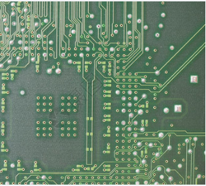
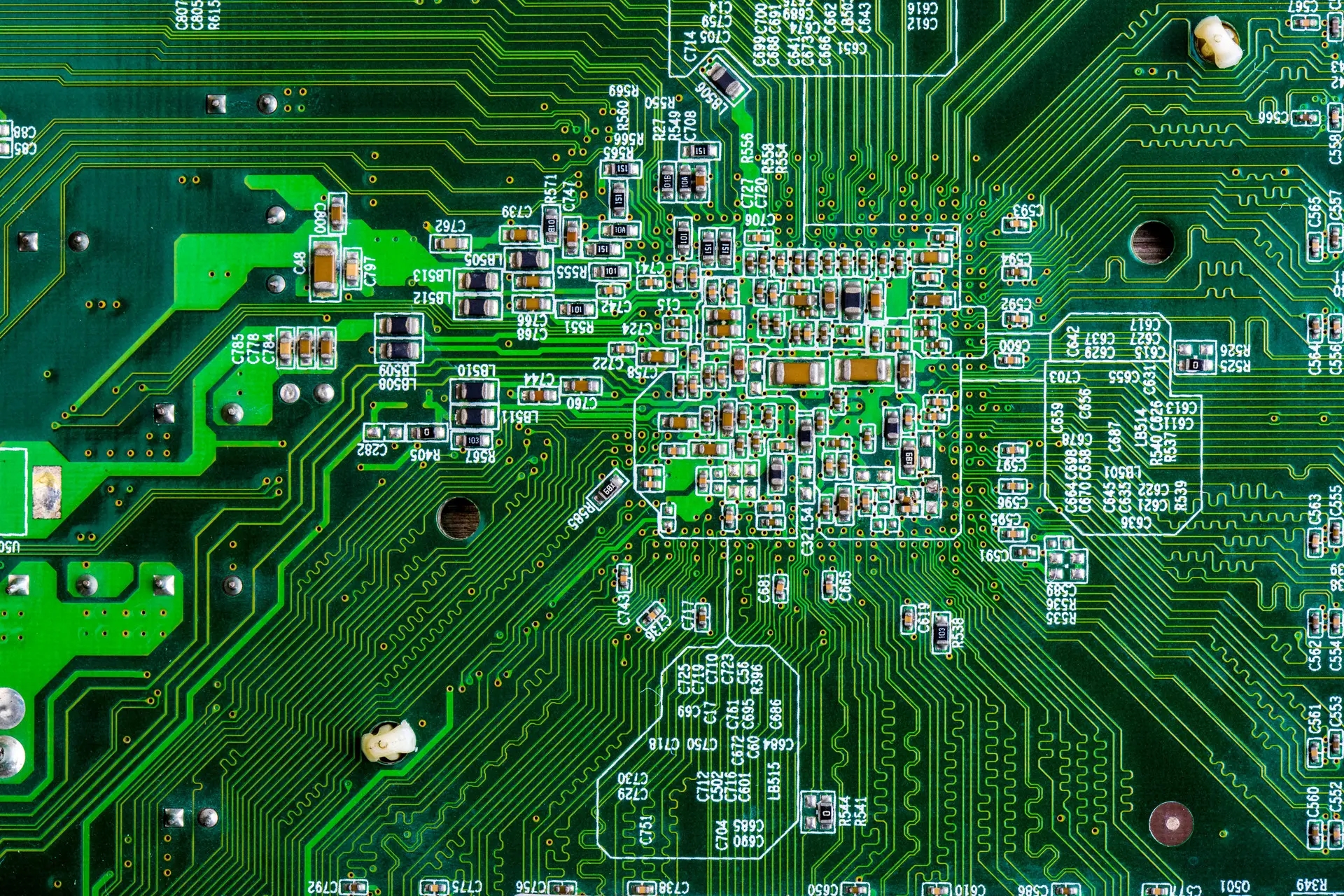
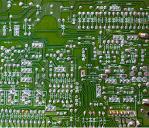
Circuit board production
In the axial force, the static component FS affects the horizontal edge Guangde cutting, while the dynamic component FD mainly affects the cutting of the main cutting edge. The dynamic component FD has greater influence on the surface roughness than the static component FS. Generally, when the diameter of the prefabricated hole is less than 0.4 mm, the static component FS decreases sharply with the increase of the diameter, while the dynamic component FD decreases more smoothly.
The wear of PCB bit is related to cutting speed, feed rate and slot size. The ratio of the drill radius to the glass fiber width has a great influence on the tool life. The larger the ratio is, the greater the tool cutting fiber bundle width is, and the tool wear also increases. In practical application, the life of 0.3mm drill tool can drill 3000 holes. The larger the drill, the fewer holes to drill.
In order to prevent layering, hole wall damage, stains and burrs during drilling, we can place a 2.5mm thick backing plate below the copper clad plate on the backing plate, and then place aluminum sheets on the copper clad plate. The role of aluminum sheets is
1. Protect the pcb board from scratches.
2. Good heat dissipation, the drill bit will generate heat when drilling.
3. Buffer function/drilling guiding function to prevent hole deviation. The method to reduce burr is to use vibration drilling technology. The carbide drill is used for drilling and has good hardness. The size and structure of the tool also need to be adjusted.


Just upload Gerber files, BOM files and design files, and the KINGFORD team will provide a complete quotation within 24h.