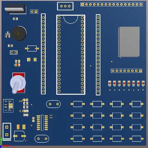
Whether the wiring of a printed circuit board can be successfully completed depends on the PCB layout. Moreover, the higher the wiring density, the more important the layout is. Almost every PCB design has encountered such a situation. When there are only a few pieces of PCB wiring left, it is found that it is impossible to arrange in any case. You have to delete a large number or all of the wiring and readjust the layout! Reasonable layout is the premise to ensure smooth PCB routing.
There is no absolute criterion to determine whether a layout is reasonable or not. Some relatively simple criteria can be used to determine the quality of a layout.
The most commonly used standard is to make the total length of flying line as short as possible.

Generally speaking, the shorter the total length of the flying wire is, the shorter the total length of the wiring is; The shorter the routing, the smaller the PCB area occupied by the routing, and the higher the routing rate. When routing is as short as possible, wiring density must also be considered.
It is a very complicated problem how to make the total length of flying line shortest and ensure that the layout density is not too high. Because adjusting the layout is to adjust the placement position of the package. A packaged pad is often associated with several or even dozens of networks at the same time. Reducing the flying wire length of one network may increase the flying wire length of another network. How to adjust the position of the package to the best point does not give a very practical standard. In actual operation, it mainly depends on the experience of the designer to check whether the fly lines displayed on the screen are simple and orderly and whether the calculated total length is the shortest.
The flying wire is the main reference standard for manual layout and PCB wiring. When manually adjusting the layout, try to make the flying wire take the shortest path. When manually wiring, each pad is often connected according to the path indicated by the flying wire. Protel's flying line optimization algorithm can effectively solve the shortest path problem of flying line connection.
The connection strategy of the fly line Protel provides two fly line connection methods for users to choose: sequential fly line and shortest tree fly line.
The flying wire connection strategy can be set on the flying wire mode page in the cabling parameter setting, and the shortest tree strategy should be selected.
It has been mentioned in the section on the display and control of dynamic flying lines that the flying line display switch is turned on after executing one of the commands to display network flying lines, display encapsulated flying lines and display all flying lines, and the flying line display switch is turned off after executing the command to hide all flying lines.
When the fly wire display switch is turned on, not only the specified network fly wire is automatically displayed on the screen, but also the fly wire connected to the package is automatically displayed whenever you manually adjust the layout and move the package position. In addition, when the package flying wire is connected, all flying wires are automatically closed except for the flying wire connected to the package.
Execute the "Edit/Move/Move Encapsulation" command. If the current flying wire display switch is on, all flying wires are automatically turned off except the flying wires connected to the encapsulation.
When the flying line strategy is "shortest tree", the starting and ending points of the flying line are changed. We know that the shortest tree flying leads do not display the flying leads according to the connection order of the pins in the network table, but determine the connection order of the package pins in a network based on the actual position of the package pins after the shortest tree calculation; When the position of a package changes, the connection order calculated according to the shortest tree theory will also change, that is, the starting and ending points of the flying lead will change. Therefore, when moving the package under the "shortest tree" strategy, the flying lead connected to the package pin will change with the change of the package position, which is called dynamic flying lead.
The dynamic flying wire adopts the flying wire strategy of finding a point nearby to connect to the network and ensuring the shortest connection length of the whole network. Therefore, the total length of the dynamic flying wire and the shortest tree flying wire provides a relatively optimal judgment standard for PCB layout.
Specifically, during layout, we ensure the effectiveness of the layout in the dynamic flying line state by the following methods.
(1) Quickly move a package within the whole board. If the flying wire connected to the package does not change greatly, it means that the number of nodes in the electrical network connected to the package pin is small, which is close to one-to-one connection. The location of the package cannot be placed arbitrarily and has a higher positioning priority. The best placement position of the package can be found by referring to the flying wire length displayed in the lower right corner of the screen.
(2) Quickly move a package within the whole board. If the flying wire connected to the package changes greatly, it means that there are many nodes in the electrical network connected to the package pin. The package may not be placed at a fixed position and has a lower positioning priority, The relative optimal placement of the package can be found according to some other criteria (such as whether the layout is beautiful or not) and referring to the length of the flying line displayed at the lower right corner of the screen.
(3) Move the package, and the position displayed in the lower right corner is relatively optimal when the length of the flying wire is the minimum.
(4) If the flying wire connection relationship between z packages remains unchanged no matter how they are moved, it indicates that the two packages have strong constraint relationship and should be placed together preferentially; If the flying wire connection relationship between a package and several packages remains unchanged no matter how it moves, it indicates that there is a strong constraint relationship between this package and these packages, and it should be placed at the center of gravity or relatively close to the center of gravity of these packages; If the flying wire can constantly change when a package moves, that is, it can always find a connection node nearby, which indicates that the package has a weak constraint relationship with all other packages, and the location of the package can be finally determined and the location can be flexible.
The dynamic fly line is undoubtedly a powerful layout tool. However, it takes time to recalculate the shortest tree of the relevant network every time the package is moved. Therefore, when using the dynamic fly line on a low-end PC or large design, the mobile package is not flexible. At this time, this problem can be solved by setting partial fly line mode and controlling the contact of display fly line network.
When moving the package under dynamic flying wire status, press R key to adjust the redisplay frequency of flying wire. The redisplay frequency is divided into five levels. When it is 1, the redisplay frequency of the flying line is the highest, which is suitable for fast machines; When it is 5, the frequency of flyline redisplay is the lowest, which is suitable for slower machines.
The dynamic flying line adopts the flying line strategy of finding a point nearby to connect to the network and ensuring the shortest connection length of the whole network. Therefore, the total length of the dynamic flying line and the shortest tree flying line provides us with the best judgment standard for layout.
To be specific, we ensure the effectiveness of PCB layout in the dynamic flying line state by the following methods.
(1) Quickly move a package within the whole board. If the flying wire connected to the package does not change greatly, it means that the number of nodes in the electrical network connected to the package pin is small, which is close to one-to-one connection. The location of the package cannot be placed arbitrarily and has a higher positioning priority. The best placement position of the package can be found by referring to the flying wire length displayed in the lower right corner of the screen.
(2) Quickly move a package within the whole board. If the flying wire connected to the package changes greatly, it means that there are many nodes in the electrical network connected to the package pin. The package may not be placed at a fixed position and has a lower positioning priority, The relative optimal placement of the package can be found according to some other criteria (such as whether the PCB layout is beautiful or not) and referring to the length of the flying wire displayed at the lower right corner of the screen.
(3) Move the package, and the position displayed in the lower right corner is relatively optimal when the length of the flying wire is the minimum.
(4) If the flying wire connection between two packages remains unchanged no matter how they are moved, it indicates that the two packages have strong constraint relationship and should be placed together preferentially; If the flying wire connection relationship between a package and several packages remains unchanged no matter how it moves, it indicates that there is a strong constraint relationship between this package and these packages, and it should be placed at the center of gravity or relatively close to the center of gravity of these packages; If the flying wire can constantly change when a package moves, that is, it can always find a connection node nearby, which indicates that the package has a weak constraint relationship with all other packages, and the location of the package can be finally determined and the location can be flexible.
Dynamic flying wire is undoubtedly a powerful PCB layout tool. However, it takes time to recalculate the shortest tree of the related network every time the package is moved. Therefore, when using the dynamic fly line on a low-end PC or large design, the mobile package is not flexible. At this time, this problem can be solved by setting partial fly line mode and controlling the contact of display fly line network.


