
Professional PCB manufacturing and assembly
Building 6, Zone 3, Yuekang Road,Bao'an District, Shenzhen, China
+86-13410863085Mon.-Sat.08:00-20:00


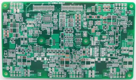
When the electronic equipment is working, it generates heat, which makes the internal temperature of the equipment rise rapidly. The direct cause of the temperature rise of the PCB is the existence of circuit power consumption devices. The electronic devices have power consumption to varying degrees. The heat intensity changes with the size of power consumption. If the heat is not dissipated in time, the equipment will continue to rise, the devices will fail due to overheating, and the reliability of the electronic equipment will decline. Therefore, it is very important to heat the PCB.

How to solve the problem of PCB heating? Such problems are generally solved by installing heat dissipation devices or fans to cool the PCB. These external accessories increase the cost and extend the manufacturing time. The addition of fans in the design will also bring instability to the reliability. Therefore, active rather than passive cooling is mainly used for PCB
There are several ways to cool the PCB for your reference:
1. Heat is dissipated through the PCB itself.
2. Add heat sink and heat conduction plate to high heating components.
3. Adopt reasonable wiring design to realize heat dissipation.
4. The devices that are sensitive to temperature should be placed in the area with the lowest temperature (such as the bottom of the equipment), and should not be placed directly above the heating devices. Multiple devices should be staggered on the horizontal plane.
5. The heat dissipation of the printed PCB in the equipment mainly depends on the air flow, so the air flow path shall be studied during the design, and the device or printed PCB shall be reasonably configured.
6. Avoid the concentration of hot spots on the PCB, distribute the power evenly on the PCB as much as possible, and keep the PCB surface temperature performance uniform and consistent.
7. Place the device with the highest power consumption and heat generation near the best heat dissipation position.
8. For the equipment cooled by free convection air, it is better to arrange the integrated circuit (or other devices) in the longitudinal or transverse way.
9. The components on the same printed board shall be arranged in zones as far as possible according to their calorific value and heat dissipation degree. The components with low calorific value or poor heat resistance shall be placed at the top (entrance) of the cooling air flow, while the components with high calorific value or good heat resistance (such as power transistors, large-scale integrated circuits, etc.) shall be placed at the bottom of the cooling air flow.
10. In the horizontal direction, high-power devices shall be arranged as close to the edge of the printed board as possible to shorten the heat transfer path; In the vertical direction, high-power devices shall be arranged as close as possible to the top of the printed PCB, so as to reduce the impact of these devices on the temperature of other devices during operation.
11. The thermal resistance between the high heat dissipation devices and the substrate shall be reduced as much as possible when they are connected. In order to better meet the requirements of thermal characteristics, some thermal conductive materials (such as a layer of thermal conductive silica gel) can be used on the bottom of the chip, and a certain contact area can be maintained for heat dissipation of the device.


Just upload Gerber files, BOM files and design files, and the KINGFORD team will provide a complete quotation within 24h.