
Professional PCB manufacturing and assembly
Building 6, Zone 3, Yuekang Road,Bao'an District, Shenzhen, China
+86-13410863085Mon.-Sat.08:00-20:00


Circuit board factory: specific introduction to ICT hardware structure
ICT is a prefix combination of three English words: information, communications and technology (ICT for short). It is a new concept and new technical field formed by the integration of information technology and communication technology. It is also the abbreviation of online tester.
This article will take the HP3070 circuit board test system as an example to introduce the basic hardware structure of the equipment system in detail.
summary
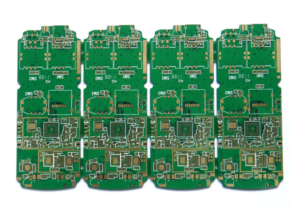
The HP3070 circuit test system is mainly used for online testing of PCBA processing boards to determine the quality of analog and digital components on PCBA boards, as well as functional testing, combinational logic testing, analog testing and bidirectional circuit testing of PCB boards. The HP3070 circuit board test system uses UNIX or MS WINDOWS operating system. Hardware mainly includes test head, controller, power supply cabinet, vacuum box, and test fixture Fixture.
Test head
The test head completes analog test and digital test. The whole test head can be divided into 2 banks, 4 modules. Each module is fully equipped with 11 cards, that is, 11 cards and card slots. The first card slot is for ASRU cards, the sixth card slot is for Control cards, and the other card slots are for Pin cards. Each module includes a Mother card, a Control card plugged into the Mother card and an ASRU card. There must be at least one Pin card.
Module card: The backplane of the module provides DC power to all cards on the module, and transmits signals and address decoding between cards.
Control card: In the side panel, the program and data are downloaded from the system control to the card, and the sixth slot of the relay Moudule is controlled according to the program.
Pin card: provides a multiplexing system for testing. Each dual density pin card provides 144 pins for testing. The test capacity of a module is 144 times 9, which is 1296 points.
ASRU caed (Analog Simulate Response Unit): simulate excitation of corresponding units, provide excitation source, vector detector, operational amplifier and other circuit measuring instruments required for analog test, and ASRU card must be in the first slot of each Moudule.
Power supply cabinet
The power supply cabinet is composed of three parts: power distribution unit PDU, system card and module power supply unit MPU. There are two programmable DC power supplies HP6624 or other configurations. Each HP6624 has four outputs, so it can provide eight groups of power supplies. The power supply output is connected to the ASRU card in the test head with a cable. The ASRU card has pins that provide PCB boards through the clamp.
PDU: Its main function is to receive power supply voltage from the outside in the range of 184V~252V, and distribute various AC and DC voltages to other parts of the system. PDU can also realize remote shutdown and voltage limit warning functions.
System card: The system card is installed on the test head and communicates with the four controllers on the test head. The system card controls whether the PDU and MPU work. The system card can also realize emergency shutdown of all AC power on the test head and the power supply of the power cabinet.
MPU: One MPU unit only provides DC voltage to one test head module, so four MPU units are required. Each MPU unit can provide five voltage values:+20V,+12V,+5V, - 10V, and - 20V.
controller
The controller, also known as system process unit - SPU, is actually a microcomputer, which controls the operation of the entire test system. It is equipped with hard disk drive and floppy disk drive and runs in HP-UNIX operating system. The control subsystem has ALN and GPIB buses.
LAN: A plug-in between the controller and the system card.
GPIB: It controls the DC power supply of the DUT and the optional test equipment on the supply and system card.
Test fixture
The test fixture is a tool for connecting the test head and PCB board or the tested power supply DUT. PCB board can be automatically or manually loaded on or off the test fixture. The test fixture can be divided into long wire fixture and short wire fixture.
Long wire clamp: the long wire clamp is a vacuum clamp, which uses twisted pair wires. One is the signal wire connected between measuring pins, and the other is the shield wire connected to the power supply and ground to prevent interference between signals. At present, this fixture is used on GenRad.
Wire breaking clamp: There are two types of wire breaking clamp, one is vacuum clamp, the other is spring clamp clamp. The signal wiring in the clamp is very short, which reduces the line loss and signal interference, and improves the test accuracy. At present, this fixture is used on HP3070.


Just upload Gerber files, BOM files and design files, and the KINGFORD team will provide a complete quotation within 24h.