(1) Ground wire loop rules:
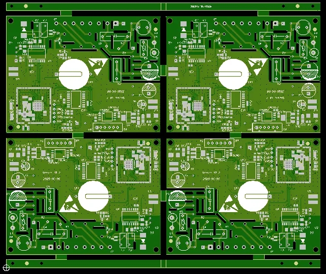
The minimum rule of the loop is that the loop area formed by the signal line and its loop should be as small as possible. The smaller the loop area is, the less external radiation is, and the less external interference is received. According to this rule, when dividing the ground plane, the distribution of the ground plane and the important signal routing should be considered to prevent the problems caused by the ground plane slotting; In the double-layer board design, when enough space is left for power supply, the left part should be filled with reference ground, and some necessary holes should be added to effectively connect the double-sided ground signals. For some key signals, ground wire isolation should be used as far as possible. For some designs with high frequency, the ground plane signal circuit should be specially considered. It is recommended to use multi-layer boards.
(2) Crosstalk control:
CrossTalk refers to the mutual interference between different networks on a PCB caused by long parallel wiring, mainly due to the distributed capacitance and inductance between parallel lines. The main measures to overcome crosstalk are:
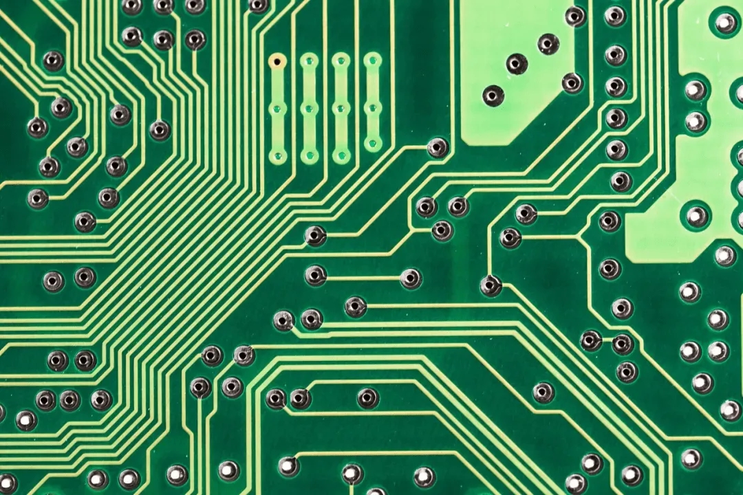
Increase the spacing of parallel wiring and follow the 3W rule.
Insert grounding isolation wire between parallel wires.
Reduce the distance between the routing layer and the ground plane.

(3) Shielding protection
The corresponding ground wire loop rules are actually designed to minimize the loop area of signals, which are often found in some important signals, such as clock signals and synchronous signals; For some signals of special importance and high frequency, the copper shaft cable shielding structure design should be considered, that is, the wires laid on the line, below the line, left and right should be separated by ground wires, and how to effectively combine the shielding ground with the actual ground plane should also be considered.
(4) Direction control rules of routing:
That is, the routing direction of adjacent layers is orthogonal. Avoid running different signal lines in the same direction at adjacent layers to reduce unnecessary inter layer interference; When it is difficult to avoid this situation due to the restriction of board structure (such as some backplanes), especially when the signal rate is high, it is necessary to consider to use the ground plane to isolate each wiring layer and the ground signal line to isolate each signal line.
(5) Open loop inspection rules for wiring:
In general, dangling lines with one end floating in the air are not allowed, mainly to avoid "antenna effect" and reduce unnecessary interference radiation and reception, otherwise unpredictable results may be caused.
(6) Impedance matching check rules:
The wiring width of the same network shall be consistent. The change of the line width will cause the nonuniform characteristic impedance of the line. When the transmission speed is high, reflection will occur. This situation should be avoided as far as possible in the design. Under some conditions, such as connector outlet and BGA encapsulated outlet with similar structure, it may be impossible to avoid the change of line width. The effective length of the inconsistent part in the middle should be minimized.
(7) Network rules for routing termination:
In high-speed digital circuits, when the delay time of PCB wiring is greater than 1/4 of the signal rise time (or fall time), the wiring can be regarded as a transmission line. In order to ensure that the input and output impedance of the signal are correctly matched with the impedance of the transmission line, various matching methods can be used. The selected matching method is related to the connection mode of the network and the topology of the wiring.
A. For point-to-point (one output corresponds to one input) connection, you can choose to start in series matching or end in parallel matching. The former has simple structure, low cost and large delay. The latter has good matching effect, but its structure is complex and its cost is high.
B. For point to multipoint connection (one output corresponds to multiple outputs), when the topology of the network is daisy chain, terminal parallel matching should be selected. When the network is a star structure, you can refer to the point-to-point structure.
Star and chrysanthemum chain are two basic topological structures. Other structures can be seen as the deformation of the basic structure, and some flexible measures can be taken to match. In actual operation, cost, power consumption, performance and other factors should be taken into account. Generally, perfect matching is not pursued, as long as the reflection and other interference caused by mismatch are limited to an acceptable range.
(8) Wiring closed-loop inspection rules:
Prevent signal lines from forming self loops between different layers. This kind of problem is easy to occur in the design of multilayer plates, and self loop will cause radiation interference.
(9) Control rules for branch length of routing:
Try to control the length of branches. The general requirement is Tdelay<=Trise/20.
(10) Resonance rules of wiring:
Mainly for high-frequency signal design, that is, the wiring length shall not be an integral multiple of its wavelength to avoid resonance.
(11) Routing length control rules:
That is, the short line rule. In the design, the wiring length should be as short as possible to reduce the interference problem caused by too long wiring. In particular, some important signal lines, such as clock lines, must be placed close to the device. For driving multiple devices, the network topology should be determined according to the specific situation.
(12) Chamfer rules:
Sharp corners and right angles shall be avoided in PCB design to avoid unnecessary radiation and poor process performance.
(13) Device decoupling rules:
A. The necessary decoupling capacitor is added to the printed board to filter the interference signal on the power supply, so that the power supply signal is stable. In multilayer boards, the position of decoupling capacitor is generally not required, but for double-layer boards, the layout of decoupling capacitor and the wiring mode of power supply will directly affect the stability of the whole system, sometimes even the success of the design.
B. In the double-layer board design, the current should be filtered by the filter capacitor before being used by the device. At the same time, the influence of the power noise generated by the device on the downstream devices should be fully considered. Generally speaking, it is better to adopt the bus structure design. In the design, the influence of the voltage drop caused by the long transmission distance on the device should also be considered. If necessary, some power filter loops should be added, Avoid potential difference.
C. In the design of high-speed circuit, whether the decoupling capacitor can be used correctly or not is related to the stability of the whole board.
(14) Device layout zoning/layering rules:
A. It is mainly to prevent mutual interference between modules with different operating frequencies, and to shorten the wiring length of high-frequency part as much as possible. Usually, the high-frequency part is arranged at the interface part to reduce the wiring length. Of course, such layout still needs to consider the possible interference of low-frequency signals. At the same time, the problem of dividing the high/low frequency part of the ground plane should also be considered. Generally, the ground of the two parts should be divided and then connected at a single point at the interface.
B. For hybrid circuits, analog and digital circuits are also arranged on both sides of the printed circuit board, with different layer wiring and layer isolation in the middle.
(15) Control rules for isolated copper area:
The appearance of isolated copper area will bring some unpredictable problems. Therefore, connecting the isolated copper area with other signals is helpful to improve the signal quality. Usually, the isolated copper area is grounded or deleted. In the actual production, PCB manufacturers added some copper foils to the vacant parts of some boards, which is mainly for the convenience of PCB processing, and also plays a certain role in preventing PCB warping.
The appearance of isolated copper area will bring some unpredictable problems. Therefore, connecting the isolated copper area with other signals will help to improve the signal quality.
The isolated copper area is usually grounded or removed. In the actual production, PCB manufacturers added some copper foils to the vacant parts of some boards, which is mainly for the convenience of PCB processing, and also plays a certain role in preventing PCB warping.
(16) Integrity rules of power and ground layers:
For areas with dense through holes, pay attention to avoid the interconnection of holes in the hollowed out areas of the power supply and the formation, which forms the division of the plane layer, thus damaging the integrity of the plane layer, and thus causing the increase of the circuit area of the signal line in the formation.
(17) Rules for overlapping power and ground layers:
Different power supply layers should avoid overlapping in space. It is mainly to reduce the interference between different power sources, especially between some power sources with large voltage difference. The overlapping problem of power plane must be avoided. If it is difficult to avoid, the interlayer can be considered.
(18) 3W rule:
In order to reduce crosstalk between lines, ensure that the line spacing is large enough. When the line center spacing is not less than 3 times the line width,
Then 70% of the electric fields can be kept from interfering with each other, which is called the 3W rule. If 98% electric fields do not interfere with each other, 10W spacing can be used.
(19) Rule 20H:
Because the electric field between the power layer and the stratum is variable, electromagnetic interference will be radiated at the edge of the board. It is called edge effect. The solution is to shrink the power layer so that the electric field is only conducted within the range of the ground plane. In the unit of one H (the thickness of the medium between the power supply and the ground), if it is reduced by 20H, 70% of the electric field can be limited to the edge of the ground plane; Shrinking 100H can limit 98% of the electric field.
(20) V. Rules:
The rules for selecting the number of layers of the PCB are: when the clock frequency reaches 5MHz or the pulse rise time is less than 5ns, the PCB must use a multilayer board, which is a general rule. Sometimes, considering cost and other factors, when using a double-layer board structure, in this case, it is better to use one side of the PCB as a complete ground plane layer.


