Detection circuit in PCB reverse design system
1 Introduction
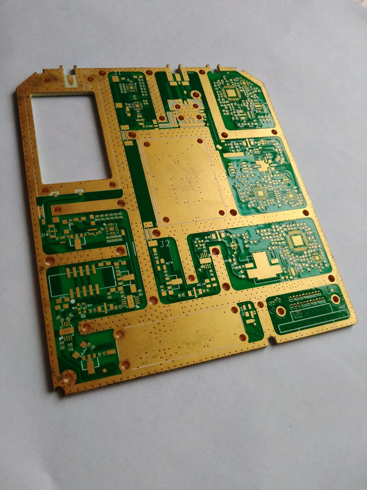
In the reverse design or maintenance of electronic equipment, electronic engineers first need to understand the connection relationship between the components on the unknown printed circuit board (PCB), so they need to measure and record the connection relationship between the pins of each component on the PCB.
The simplest method is to set the multimeter to "short circuit buzzer", use two pens to measure the connection between pins one by one, and then manually record the on/off status between "pin pairs". In order to obtain the complete set of connection relations among all "pin pairs", the "pin pairs" under test must be organized according to the combination principle. When the number of components and pins on the PCB is large, the number of "pin pairs" to be measured will be very large. Obviously, if this work is done by manual methods, the workload of measurement, recording and proofreading will be very heavy. And the measurement accuracy is low, as is known to all, the general multimeter pen between the resistance impedance value to about 20 ohms, the buzzer will still make a sound, expressed as a path.
In order to improve the measurement efficiency, it is necessary to realize the automatic measurement, recording and proofreading of the element "pin pair". Therefore, the author designed a path detector controlled by a microcontroller as the front-end detection equipment, and designed a set of powerful measurement and navigation software for back-end processing, to realize the automatic measurement and recording of the path relationship between the components on PCB. This paper mainly discusses the design idea and technology of path detection circuit to realize automatic measurement.

The premise of automatic measurement is to connect the pin of the measured element into the detection circuit, so that the detection equipment is set up a number of measuring heads, through the cable out, the measuring head can be connected to a variety of test fixtures and element pins to establish a connection, the number of measuring heads determines the number of pins connected to the same batch of detection circuit. Then under the program control, the detector will be measured "pin pair" into the measurement path one by one according to the combination principle. In the measurement path, the on/off condition between the "pin pairs" is presented as whether there is resistance between the pins, and the measurement path converts it into a voltage quantity, thus judging the on/off relationship between them and recording it.
Based on this idea, PCB path detection circuit should realize three main functions:
· Automatically select and measure the "pin pair" under test;
· Automatically judge the path relationship between "pin pairs";
· Automatic recording of measurement results.
2. Automatic selection and measurement of pin pairs under test
2.1 Automatic switching of pin pairs under test
In order to enable the detection circuit to select different pins from many measuring heads of connected component pins in turn according to the combination principle for measurement, the corresponding switch array can be set, different switches can be opened/closed by the program, the component pins can be switched into the measurement path, and the on/off relationship can be obtained. As the measured voltage is an analog quantity, the analog multiplex switch should be used to form a switch array, and the idea of switching the pin under test should be realized with the analog switch array.
2.2 Measurement of the on/off relationship
The design principle of detection circuit. In the figure, two groups of analog switches in boxes Ⅰ and Ⅱ are configured in pairs: ⅰ-1 and ⅱ-1, ⅰ-2 and ⅱ-2,...... , Ⅰ-N and Ⅱ-N. Whether the analog multiplexer switch is closed or not is controlled by the program through the decoding circuit shown in Figure 1. In the Ⅰ and Ⅱ analog switches, only one switch can be closed at most. For example, to detect whether there is A path relationship between measuring head 1 and measuring head 2, make the switch Ⅰ-1 and Ⅱ-2 close, and form A measuring path between point A and ground through measuring head 1 and 2. If it is a path, the voltage at point A is VA=0; If the link is open, VA> is displayed. 0. The value of VA is the basis for judging whether there is a channel relationship between the measuring head 1 and 2. In this way, the on/off relationship between all pins attached to the measuring head can be measured in an instant according to the combination principle. Since this measurement process is carried out between the pins of the components in the test fixture, the author calls it the in-clip measurement.
If the pin of the component is not clip-on, it must be measured with a marker. Connect one meter pen to an analog channel and ground the other one. Then the measurement can be carried out as long as the control switch Ⅰ-1 is closed, which is called pen measurement. The circuit can also instantaneously complete the measurement between all the clip-on pins connected to the measuring head and the unclip-on pins touched by the grounding pen. At this time, it is necessary to control the closure of the switches in the Ⅰ circuit in turn, while the switches in the Ⅱ circuit are always disconnected. This measurement process can be called the pen clip measurement.


