With the appearance of 100 megabit bus, when the signal edge rate reaches picosecond level, the system performance depends more on the front-end design, requiring accurate timing analysis and calculation at the beginning of design. Timing analysis and signal integrity are inseparable, and good signal quality is the key to ensure timing relationship. The signal quality problems caused by reflection, crosstalk and other phenomena are likely to bring the timing deviation and disorder, we must consider the two must be combined in the design. The following patch processing manufacturer Xiaobian to explain how to high-speed PCB designtiming analysis and how to quickly repair the circuit board related knowledge.
1. How to check the circuit board quickly
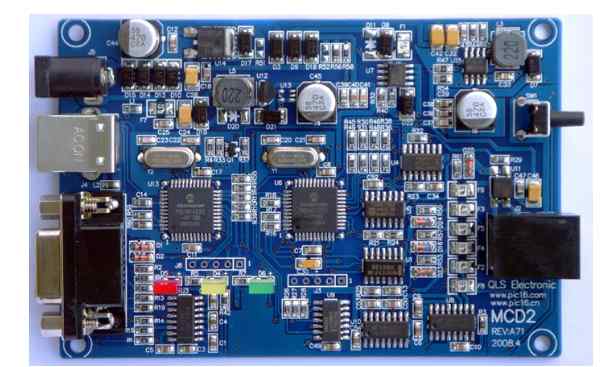
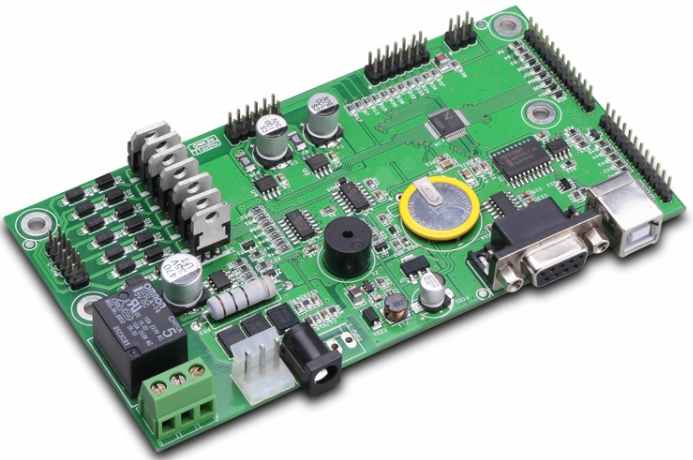
Making PCB board is not a simple process to finish the board, drill a hole on the components. The production of PCB is not difficult, but the difficulty lies in the troubleshooting after the production. Whether it is an individual hobbyist or an industrial engineer, it is quite a headache for PCBA circuit boards to encounter problems when debugging, just like programmers encounter bugs. Some people have a strong interest in debugging PCBA circuit board, just like programmers in solving bugs, common PCBA circuit board problems and many, common problems in addition to circuit board design, damage to electronic components, circuit short circuit, quality of components, PCBA circuit board fault is not a few. Damaged diode ring color resistance Common PCBA circuit board faults are mainly concentrated on the components, such as capacitor, resistor, inductor, diode, audion, field effect tube, etc., the obvious damage of integrated chip and crystal oscillator, and the more intuitive method to judge the failure of these components can be observed through the eyes.
The surface of the electronic components with obvious damage has obvious cautery marks. Such faults can be solved directly by replacing the faulty component with a new one. Suspected damaged component? In fact, it is not the component damage, of course, not all the damage of electronic components can be observed with the naked eye, such as the resistance, capacitor, two triode, etc., in some cases the damage can not be seen from the surface, the need to use professional inspection tools for maintenance, commonly used inspection with: For multimeters and capacitor meters, if the voltage or current of an electronic component is detected to be out of the normal range, it indicates that the component or the previous component has a problem. Directly replace the component and check whether it is normal. If a circuit board component with no damage in appearance and no fault can be detected, it can be detected no matter by eye observation or instrument detection. However, sometimes when we give components on PCB board, there will be no problem detected, but the circuit board cannot work normally. Many novices have no choice but to build a new board or buy one.
In fact, in many cases, components in the installation process, because of the coordination of each component, there may be unstable performance. Circuit board circuit block division in this case, the instrument has been unable to play a role in helping, you can try to judge the possible range of fault according to the current and voltage, as far as possible to reduce, experienced engineers may be able to quickly judge the fault area, but the specific component which is broken is not 100% sure. The only option is to try to replace the suspect component until the faulty component is found. Last year, the motherboard of my notebook was flooded, and when I was repairing the master, I also encountered that the fault could not be detected, and I replaced the components three times in the maintenance process, which were power supply chip, diode, USB charging component (that is, the blue jack of the notebook, which can charge the device when it is off). Finally, I replaced the suspicious chip through a wave of detection and investigation. Finally determined that a component on the side of the south bridge chip short-circuited.
Circuit board flying line above is actually the problem of electronic components, of course, since the PCBA circuit board as a component of the landing point, then the circuit board fault must also exist, the simplest example is dead tin plating parts, because of the production process, in the process of PCB corrosion, there may be broken line problems. In this case, if you can't fill the line, you can only use fine copper wire flying line. In the case that PCBA circuit board fault is not obviously damaged, it is indeed very troublesome to check. In the process of troubleshooting, there will be a spirit of concentration, and after finding out the problem, there will be a sense of achievement. Programmers solve bugs in this mood, I often like to check some difficult to repair boards, I think it is a kind of fun.

2. How to conduct timing analysis for high-speed PCB design
Timing analysis is an important part of high speed PCB design for digital system design engineers. Especially with the appearance of 100 megabit bus, the signal edge rate reaches picosecond level, the system performance depends more on the front-end design, requiring accurate timing analysis and calculation at the beginning of the design. Timing analysis and signal integrity are inseparable, and good signal quality is the key to ensure timing relationship. The signal quality problems caused by reflection, crosstalk and other phenomena are likely to bring the timing deviation and disorder, we must consider the two must be combined in the design.
The starting point of time sequence analysis is to establish or maintain time relationships based on signals to determine the design scheme. This method runs through the whole design process, including IC design, board level design and system design. Time of flight is the difference between the time the signal is sent and the time the signal is stable at the receiving end. It is used to describe the delay caused by wiring and load. In the case of low speed, approximate method can be used to determine, but in the case of high speed PCB design, due to the influence of load and transmission line effect, simulation method must be used to determine. After determining the flight time, the timing sequence calculation can be implemented by tabular or manual methods to check whether the signal meets the signal sampling and holding requirements. Similarly, reverse the process to obtain wiring length rules. The feature of the common clock mode is that the receiving and sending clocks are provided by the common clock source. It has two characteristics: one is that the data is required to reach the receiving end within one cycle; the other is that the clock difference has a great impact on the timing.
Usually, when the clock and data are driven by the same type of interface, the timing calculation only needs to consider the difference between them. If this is not the case, the difference (such as the wiring length) needs to be adjusted according to the flight time. In this case, the common sense of the data clock wiring method in PCB designbecomes invalid. In the design, other factors such as switching noise, intercode interference, non - ideal loop and so on have influence on signal phase. Therefore, on the one hand, we should reasonably add the design margin in the timing design, on the other hand, we also need to adopt other design methods to reduce the influence of interference.


