
Professional PCB manufacturing and assembly
Building 6, Zone 3, Yuekang Road,Bao'an District, Shenzhen, China
+86-13410863085Mon.-Sat.08:00-20:00

PCB design causes thermal hysteresis of voltage reference?
Whenever you need to place a reference voltage in a PCB layout, it must be super stable against temperature fluctuations and external noise. The drift of the reference voltage source will produce small voltage error, which is unacceptable in some precision measurement systems, precision voltage regulators and high-resolution converters. The reference voltage circuit has a specific quantity, which defines how the temperature cycle affects the reference voltage, which is called thermal hysteresis.
For semiconductor components, thermal hysteresis is inevitable only because of the planar structure of semiconductor devices. Although thermal hysteresis cannot be completely prevented, it can be suppressed by performing appropriate PCB installation and electrical testing before deploying the product to the final environment. This is what causes thermal hysteresis and how to eliminate it when preparing to deploy a new solution.
What is thermal hysteresis?
Technically, due to the change of some variables or system parameters (including temperature and the quantity changing with temperature), any quantity that can be physically measured will show hysteresis during the measurement process. Generally, the thermal hysteresis is discussed by separating the freezing point and melting point of ice crystals in solutions containing antifreeze protein/glycoprotein. As the solution temperature cycles between the limit values, the freezing temperature and melting temperature will change slightly. Conceptually, thermal hysteresis can be compared with hysteresis, where the circulating magnetic field will leave some residual magnetization.
Thermal hysteresis in the circuit
In electronic products, thermal hysteresis is used to describe the accuracy of reference voltage. These are precision circuits and equipment used to provide stable comparisons for voltage measurements in some other circuits. Some circuits and components that need to stabilize the reference voltage are:
Analog to Digital Converter (ADC) and Digital to Analog Converter (DAC): These two circuits use reference voltages to set quantization values.
Low dropout (LDO) regulator: the reference voltage is used as an input of the error amplifier to detect when the output voltage of the regulator drops too low. The error amplifier then modulates the MOSFET to correct the output voltage to the desired value.
Comparator: The reference voltage source provides the basis for the high and low thresholds of the comparator and its switching hysteresis. This can be provided by batteries, zener diodes, or silicon bandgap reference sources.
Formal definition
The form of thermal hysteresis is formally defined as the change of output voltage at ambient temperature (+25 ° C) before and after device cycling in the whole operating temperature range. Thermal hysteresis in voltage reference circuits is usually measured in ppm/° C. This is the output reference voltage due to Δ The amount of change due to temperature cycling in T. In fact, when the temperature Δ When T is cycled, this is a permanent change in the output voltage of the reference voltage circuit.
If the device cycles between its low temperature rating and high temperature rating (for example, the temperature range of many components is - 40 ° C to 125 ° C), the total change of output can reach~1 mV for a typical bandgap reference voltage circuit. The hysteresis value of high-precision circuit correctly installed on PCB can be as low as~105 ppm in the whole operating temperature range. Note that long term drift can occur in these circuits even if the temperature of the circuits remains constant.
What causes thermal hysteresis?
The thermal hysteresis is caused by the mechanical stress accumulated on the semiconductor tube core during the temperature cycle. The stress distribution and how to release the stress from the device depend on whether the chip was previously at a higher or lower temperature and the past stress history in the device. Due to thermal expansion and contraction, stress accumulates and solidifies at different locations on the die.
Once the equipment with reference voltage circuit is off the production line, a short test is usually conducted under standard environmental conditions. What happens next may exert pressure on the semiconductor die and cause the output of the reference voltage circuit to change in the following ways:
Heating and cooling during packaging: When placing the mold in the package, put it into the high-temperature epoxy package. The package is then cooled and returned to ambient temperature. In this process, the stress will accumulate on the mold.
Welding during assembly: wave soldering requires heating the equipment to high temperature and maintaining it for a period of time. After cooling, some stress will accumulate in the mold. Manual welding will not heat the whole equipment to the extent that a large amount of stress accumulates.
Heating during operation: when the equipment works on PCB, the temperature will inevitably change. Heat may flow to the reference voltage circuit from other components on the board or from the external environment.
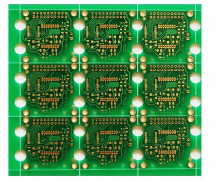
Placing notches around parts prone to thermal hysteresis is a way to increase the stiffness of the substrate under the part. In addition, place the device away from the center of the PCB board. Both methods have been proved by experiments to reduce stress accumulation and thermal hysteresis.
The edge of the plate provides a hard mounting surface to prevent output voltage changes due to thermal hysteresis.
Finally, in order to reduce the stress in the die and force the reference voltage circuit to stabilize to its long-term output, the circuit can be cycled repeatedly when the assembled PCB is running. This may require multiple cycles, but some component manufacturers' measurements of the reference voltage show that after repeated cycles, the hysteresis window decreases with time. The PCB processing factory explained the thermal hysteresis of the voltage reference caused by PCB design, and what is the thermal hysteresis.


Just upload Gerber files, BOM files and design files, and the KINGFORD team will provide a complete quotation within 24h.