
Professional PCB manufacturing and assembly
Building 6, Zone 3, Yuekang Road,Bao'an District, Shenzhen, China
+86-13410863085Mon.-Sat.08:00-20:00

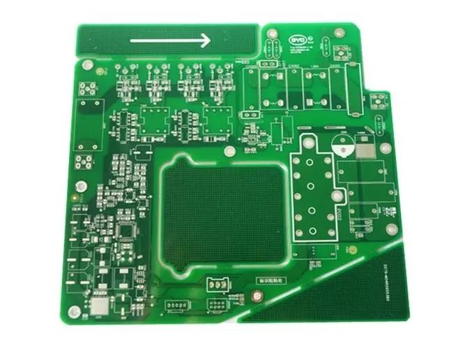
PCB designers explain some principles of SMT-PCB design
PCB assembly and PCB processing manufacturers introduce PCB designers to explain some principles of SMT-PCB design
The design of printed circuit board is based on the circuit schematic diagram to realize the functions required by the circuit designer. The design of printed circuit board mainly refers to layout design, which needs to consider the layout of external connections. The optimal layout of internal electronic components, the optimal layout of metal wiring and through-hole, electromagnetic protection, heat dissipation and other factors. Excellent layout design can save production costs and achieve good circuit performance and heat dissipation. Simple layout design can be realized by hand, while complex layout design needs to be realized by computer aided design (CAD)
1、 Layout of components on SMT-PCB
When the circuit board is placed on the conveyor belt of the reflow soldering furnace, the long axis of the components should be perpendicular to the transmission direction of the equipment, so as to prevent the components from drifting or "standing on the board" during the welding process.
2. The components on the PCB should be evenly distributed, especially the high-power components should be dispersed to avoid local overheating stress on the PCB during circuit operation, which affects the reliability of solder joints.
3. For components mounted on both sides, the components with large volume on both sides should be staggered, otherwise the welding effect will be affected due to the increase of local heat capacity during the welding process.
4. PLCC/QFP and other devices with pins on four sides cannot be placed on the wave soldering surface.
5. The long axis of the SMT large device installed on the wave soldering surface should be parallel to the flow direction of the solder wave peak, which can reduce the solder bridge between electrodes.
6. The large and small SMT components on the wave soldering surface shall not be arranged in a straight line, but shall be staggered, so as to prevent false soldering and solder skips caused by the "shadow" effect of solder wave during welding.
2、 Pad on SMT-PCB
For SMT components on the wave soldering surface, the pads of larger components (such as transistors, sockets, etc.) should be appropriately enlarged. For example, the pads of SOT23 can be lengthened by 0.8-1 mm, which can avoid empty soldering due to the "shadow effect" of components.
2. The size of the pad shall be determined according to the size of the component. The width of the pad is equal to or slightly greater than the width of the electrode of the component, and the welding effect is the best.
3. Between two connected components, it is necessary to avoid using a single large bonding pad, because the solder on the large bonding pad will connect the binary components to the middle. The correct way is to separate the bonding pads of the binary components, and connect the two bonding pads with thin wires between them. If the wires are required to pass through a large current, several wires can be connected in parallel, and the wires are covered with green oil.
4. There shall be no through-hole on or near the bonding pad of SMT components, or the solder on the bonding pad will flow along the through-hole after melting in the REFLOW process, resulting in faulty soldering, less tin and short circuit on the other side of the board. PCB assembly and PCB processing manufacturers introduce PCB designers to explain some principles of SMT-PCB design.


Just upload Gerber files, BOM files and design files, and the KINGFORD team will provide a complete quotation within 24h.