
Professional PCB manufacturing and assembly
Building 6, Zone 3, Yuekang Road,Bao'an District, Shenzhen, China
+86-13410863085Mon.-Sat.08:00-20:00

Electronic engineer explains RF PCB layout guide sharing
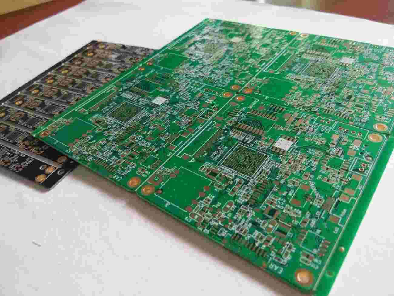
1、 Principles of RF layout:
Component layout is the key to an excellent RF design. The most effective technology is to first fix the components on the RF path, and adjust their orientation to minimize the length of the RF path, keep the input away from the output, and separate the high power circuit and low power circuit as far as possible.
The most effective circuit board stacking method is to arrange the main ground (main ground) on the second layer below the surface layer, and try to lay the RF line on the surface layer. Minimizing the size of vias on the RF path can not only reduce the path inductance, but also reduce the number of solder joints on the main ground, and reduce the chance of RF energy leakage to other areas in the laminate.
1. Isolate the high power RF amplifier (HPA) and low noise amplifier (LNA) as far as possible, that is, keep the high power RF transmitting circuit away from the low power RF receiving circuit. Usually, the low-noise amplifier circuit can be placed on one side of the PCB, while the high-power amplifier can be placed on the other side.
2. RF output usually needs to be far away from RF input
3. The decoupling of chip and power supply is also extremely important.
4. Sensitive analog signals should be as far away from high-speed digital signals and RF signals as possible.
5. Make sure that the high power area on the PCB has at least one whole ground, and there should be no via on it. Of course, the more copper sheets, the better.
2、 Principles of RF wiring:
1. The decoupling of chip and power supply is very important. Many RF chips integrated with linear circuits are very sensitive to power supply noise. Generally, each chip needs to use up to four capacitors and an isolation inductor to ensure filtering out all power supply noise.
2. The inductors shall not be placed together in parallel, because it will form an air core transformer and induce each other to generate interference signals, so the distance between them shall be at least equal to the height of one of the devices, or arranged at right angles to minimize their mutual inductance.
3. RF lines shall be kept away from analog lines and some critical digital signals. All RF wiring, pads and components shall be filled with copper grounding shields as much as possible and connected to the main ground as much as possible.
4. RF and IF wiring shall be crossed as far as possible and separated from each other by a piece of land as far as possible.
5. The shielding cover shields the RF energy in the RF area. The digital signal line entering the metal shielding cover should go through the inner layer as far as possible, and the PCB below the line layer should be the layer.
6. The DC current of most circuits in cellular phones is relatively small, so the wiring width is usually not a problem. However, a large current line as wide as possible must be separately routed for the power supply of the high-power amplifier to minimize the transmission voltage drop.
7. To avoid too much current loss, multiple vias are required to transfer current from one layer to another.
8. Make sure that through vias do not transfer RF energy from one side of the board to the other. The common technique is to use blind holes on both sides. Through vias can be arranged in the area where both sides of the PCB are free from RF interference to minimize the adverse effects of through vias.
9. Avoid straight corners of wiring, and try to use arc or 45 degree wiring to prevent impedance discontinuity.


Just upload Gerber files, BOM files and design files, and the KINGFORD team will provide a complete quotation within 24h.