
Professional PCB manufacturing and assembly
Building 6, Zone 3, Yuekang Road,Bao'an District, Shenzhen, China
+86-13410863085Mon.-Sat.08:00-20:00

What is the use of window opening in PCB design? How to design
PCB manufacturers, PCB designers and PCBA manufacturers explain to you what is the use of windowing in PCB design and how to design
The design of printed circuit board is based on the circuit schematic diagram to realize the functions required by the circuit designer. The design of printed circuit board mainly refers to layout design, which needs to consider the layout of external connections. The optimal layout of internal electronic components, the optimal layout of metal wiring and through-hole, electromagnetic protection, heat dissipation and other factors. Excellent layout design can save production costs and achieve good circuit performance and heat dissipation. Simple layout design can be realized by hand, while complex layout design needs to be realized by computer aided design (CAD)
What is window opening?
Normally, the leads on the PCB are covered with oil to prevent short circuits and damage to the equipment. The so-called window is to remove the coating layer on the wire so that the wire can be exposed to tin.
What's the use of windowing in PCB design?
PCB design can not only realize the PCB as a plug and play plug-in, but also increase the thickness of solder to achieve the purpose of excessive current.
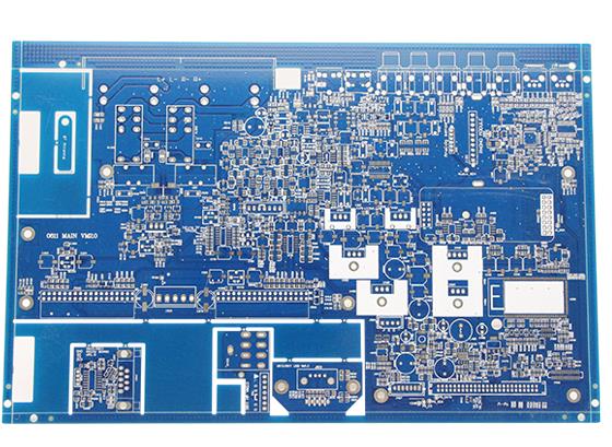
As shown in the figure above, the window opens. PCB windowing is not uncommon. The most common one is probably the memory module. Anyone who takes a computer apart knows that there is a golden finger on the memory strip.
Here, Golden Finger is the open window, plug and play.
Another common function of window opening is that the later iron increases the thickness of copper foil, which facilitates excessive current, which is more common on power boards and motor control boards.
How to open windows in PCB design?
In PCB design, threading and windowing can be set on the TOP/BOTTOM SOLDER layer.
TOP/BOTTOM SOLDER.
Soldering resistance green oil window can be set at the butt pad, via and non electrical wiring of this layer.
By default, the bonding pad will open a window in PCB design (OVERRIDE: 0.1016mm), that is, the bonding pad will expose copper foil, expand 0.1016mm, and solder is applied during wave soldering. It is recommended not to make any design changes to ensure weldability;
2. In PCB design, via will be windowed by default (OVERRIDE: 0.1016mm), that is, via will expose copper foil, expand 0.1016mm, and solder at wave crest. If the design is to prevent SOLDER from being pasted on SOLDER MASK, you must select the PENTING option of SOLDER MASK to close SOLDER MASK.
3. In addition, non electrical wiring can also be conducted separately in this layer, so that the green oil can be blocked and the window can be opened accordingly. If it is on copper foil wire, it is used to enhance the capacity of conductor overcurrent. Tin is added during welding. If a non copper foil wire is used, usually for logo and special character screen printing, it can be omitted to produce a character screen layer. PCB manufacturers, PCB designers and PCBA manufacturers will explain to you what is the use of windowing in PCB design and how to design.


Just upload Gerber files, BOM files and design files, and the KINGFORD team will provide a complete quotation within 24h.